
Sheet Metal Fabrication Design Engineering Project management Assembly Rapid Prototyping Packaging Shipping & Delivery
CNC Machining Design Engineering Project management Assembly Rapid Prototyping Packaging Shipping & Delivery
Plastic Injection Molding Design Engineering Project management Assembly Rapid Prototyping Packaging Shipping & Delivery
Somehow, on every sheet metal drawing, one number ends up deciding everything else. Thickness. Go up and the part stiffens, gets heavier, and the material line on your quote creeps upward with it. Go down and you save money — right up to the week a cover flexes in the field, or a formed edge shows hairline cracks straight off the press brake. Getting this number right has nothing to do with grabbing the biggest figure your budget can carry; it is about finding the spot where strength, weight and unit cost all survive contact with your actual application.
Picture thickness as the hub of a triangle. Stiffer, tougher parts generally need more metal, and more metal means three things at once: more shipped weight, more raw-material spend, more minutes booked on the cutter and the press brake. Thin gauge swings the other way — cheap, light — but it quietly caps how deep you can bend, how much load the part carries, and whether the panel reaches your customer dented or straight.
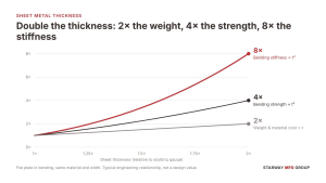
People tend to assume this trade-off runs on a straight line. It doesn’t, and that single misunderstanding costs real money. Double your thickness and sure, weight per square meter roughly doubles. Bending stiffness, though, climbs faster than weight does. Which means a cleverly formed profile in thin gauge can beat a lazily designed flat plate in heavy material, and beat it on cost and shipping weight besides. Next time somebody reaches for “one gauge heavier, just to be safe,” remember: that may be the most expensive six words in sheet metal design.
At STARWAY MFG GROUP, for instance, workable laser-cutting thickness shifts with material grade, part geometry, edge requirements, and which machine gets assigned to the job. So the useful question was never “how thick can we afford.” It is: what is the thinnest section that still survives assembly, function and years of service?
Before anybody compares numbers, an unglamorous chore comes first: getting everyone onto the same ruler.
Gauge numbers are odd creatures — neither standard nor metric, values owing nothing to either system. Nothing about the bare number 18 hints at what it means on its own.
Pull up a typical chart and the number resolves. Two data points worth keeping:
Messier still: several gauge systems share the workplace today, and some designations belong to one metal only. So before trusting a gauge figure, pull up the chart for the metal in question. And on your own drawings, write millimeters or inches outright. Gauge can stay the bar-talk shorthand it is. “Ask for 18, get one sheet” is fine; assuming two suppliers mean the same sheet is not.
Memorize one direction and the rest follows: bigger gauge number, thinner sheet. Mild steel across the working range:
The same chart’s aluminum column stops at 16 gauge — 7 at .1443 inch (3.665 mm), 8 at .1285 (3.264 mm), 9 at .1144 (2.906), 10 at .1019 (2.588), 11 at .09074 (2.305), 12 at .08081 (2.053), 14 at .06408 (1.628), 16 at .05082 (1.291). Nothing thinner gets charted for aluminum, which quietly tells you how thin aluminum sheet is ordered in practice anyway. Numbers above come from an industry gauge reference chart (Metal Supermarkets gauge chart); check them against the standard governing your material.
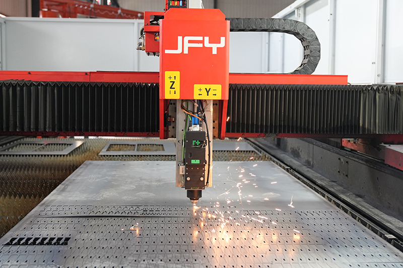
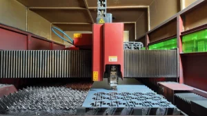
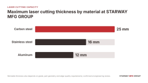
Inside STARWAY MFG GROUP’s laser cutting range, ceilings break out by material family. Carbon steel goes thickest — up to 25 mm. Stainless stops at 16 mm; aluminum, at 12 mm.
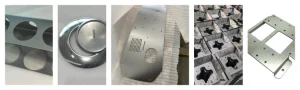
Carbon steel — Q235, Q345, SPCC, SPHC — is the workhorse behind brackets, panels, structural parts. Q235 welds well, costs little, shows up everywhere; Q345 brings the higher strength and good toughness when the structure actually carries load. Stainless (SS201, SS304, SS316, SS430) is the branch you take when corrosion resistance drives the decision — SS304 especially, the common grade for food and medical applications and other corrosion-resistant parts. Aluminum (5052, 5083, 5754, 6061) is where you go when weight and corrosion resistance both matter at once; AL5052, with excellent corrosion resistance and good formability, turns up constantly in sheet metal enclosures.
The published material data on STARWAY MFG GROUP’s materials pages shows why trade-offs shift from grade to grade even at one shared nominal thickness. Density, strength, working temperature — they all move with the grade:
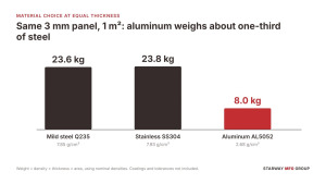
Run the density column and the gap is impossible to miss. At identical thickness, an AL5052 part at 2.68 g/cm³ carries roughly a third of what the same part weighs in carbon steel at 7.85 g/cm³. A 3 mm aluminum panel and a 3 mm steel panel are not the same part wearing different hats — they are two different answers to a design question.
Your grade choice quietly locks which finishing options can protect or decorate that thickness in the first place. The material data published on STARWAY MFG GROUP’s pages pairs each grade with its usual routes (reference the standard that applies before committing):
A powder-coated steel enclosure and an anodized aluminum one reach “good looking and corrosion-safe” by completely different roads.
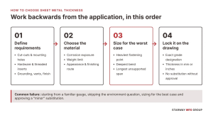
Work backwards from the application. The sequence matters more than any single step in it.
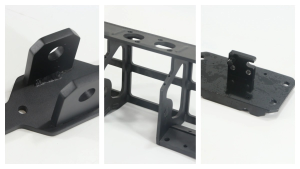
Requirements come down on paper first. A typical custom enclosure for electrical or industrial equipment — cabinet, cover, mounting panel, whatever the shape — generates a list like: precise cut-outs, mounting-hole locations, grounding areas, ventilation openings, hardware insertion, powder coating, assembly-ready interfaces. Sounds like generic checklist filler until you read it again through the eyes of thickness. Threaded inserts have to grip actual material; ask a thin sheet to hold torque and it simply will not.
Metal gets picked after that, on environment and function rather than habit. Corrosion exposure, weight caps, appearance targets, a finishing route (paint, powder coat, anodizing) — by the time those are answered, the steel-versus-stainless-versus-aluminum fight is usually already over, before anyone says a thickness out loud.
Then sizing. And here the instinct to design around the easy case gets people burned, so go the other way: find the worst assembly fastening point, the deepest bend, the tallest unsupported span. Design for those. The easy case survives on its own.
Last, the drawing itself — exact material designation, actual thickness stated outright, and one note in the margins: any substitution, other grade or other gauge, comes to you for approval. Not decided quietly on the shop floor.
Why all this fuss over sequence? Because the familiar failure is the sequence run backwards: start from the gauge you know, skip the environment question, size to a best-case load, then wave through a “minor” substitution on the purchase order. Four mistakes, each free to fix at the drawing stage — and expensive as anything after the first shipment.
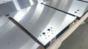
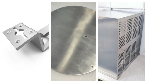
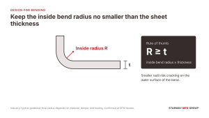
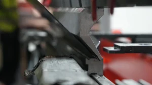
Thickness decides what the factory can physically do with your part at all. The bend radius rule everybody lives by: keep the inside bend radius no smaller than the material thickness. Forming capacity comes next — STARWAY MFG GROUP’s CNC bending handles material up to 8 mm (mild steel) at nominal bending tolerances of ±0.05 mm, so if your design needs thicker plate formed, raise it early in review and let the process route get planned rather than improvised.
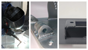
Cutting tolerance deserves its own moment. Up through 3 mm of sheet, ±0.1 mm is the standard call. Past 3 mm? Budget ±0.2 mm or looser — engineering review will pin down what actually applies. One drawing habit pays for itself here: mark the critical holes and mating features explicitly, since a tight fit hole often ends up drilled or reamed after cutting rather than trusted to the laser alone. Joining next. MIG, TIG and spot welding all sit on the menu for sheet assemblies — except weld schedules and heat input behave nothing like the same way at thin gauge as at plate. What keeps welds strong and durable is thickness consistency across the assembly.
One last interaction earns attention at the drawing stage, because it sneaks up on people: finishing adds to the stack. A powder coat or plating layer changes clearances at mating features, and thick plate holds a different cutting tolerance than thin sheet. The moment to reconcile those layers is before the first cut. Not at first-article inspection, when every fix costs a re-run.

There is no single price-per-kilogram formula that predicts your quote, and the reason is structural: quotations get reviewed part by part. Material grade, thickness, quantity, profile complexity, small holes, narrow gaps — everything feeds the manufacturing review. Critical hole sizes, hole-to-edge distances, anything that has to fit another component: identify them on the drawing, and the review determines whether a feature comes off the laser or gets finished by secondary machining. Include subsequent bending and welding in the request too, so the quote covers the complete part instead of one lonely operation.
For orientation, STARWAY MFG GROUP’s materials pages publish reference price ranges (numbers first, caveat after — you will want the caveat):
Before any of those numbers sneak into a budget, know what they are: reference figures from published material tables, not live market prices. They show the direction of the trade-off, not your quote. Heavier gauge pays more in material, thicker plate takes longer to cut, end of story.
The sneaky money hides in two words from the review list above — quantity and complexity — which decide more of your unit price than most buyers expect. Order the same 2 mm panel at 100 pieces, 1,000, or 10,000 and it moves through review as three different jobs, since setup, nesting and process planning amortize differently at each batch size.

Thickness decisions get easier the moment somebody downstream actually reads your drawing — not after the first sheet reaches a cutting table. Metal laser cutting covers carbon steel, stainless steel, aluminum, brass and copper, and every incoming drawing goes through a consulting team first: can the geometry survive cutting, bending, welding — inside bend radii, tolerance callouts, the secondary operations hanging off the part? If the thickness question is still open on arrival, it gets settled during that review or on a prototype (those land in a week or two).


The fastest route to a real number is a drawing with nothing left implied. Material by exact designation. Thickness stated outright. Critical holes, mating interfaces and finishing calls marked as what they are. Bending and welding named in the request, not assumed. A drawing complete to that standard gets priced as one job instead of three operations. Unsure whether yours clears the bar? The RFQ checklist for an accurate quote on STARWAY MFG GROUP’s blog goes through it line by line.
Q1: How thick is sheet metal typically available for fabrication?
A1: Depends twice over — on the metal, and on the process doing the cutting. Laser cutting at STARWAY MFG GROUP reaches 25 mm in carbon steel, 16 mm in stainless, 12 mm in aluminum. In practice those ceilings almost never get tested. Most real work — brackets, covers, panels, enclosures — sits a few millimeters at most, in thin gauge. Plate shows up only when a part genuinely carries structure.
Q2: Is a higher gauge number thicker or thinner?
A2: Thinner. The scale runs opposite to its own appearance, so the first guess is nearly always wrong. Steel scale: 7 gauge is about 4.55 mm; by 20 gauge you are down near 0.91 mm. The subtler trap — the same number means different things in different metals. 18 gauge: in steel, 0.0478 inch. In aluminum, 0.0403. Ask two suppliers for “18” and you can end up buying two different sheets. So the drawing speaks millimeters or inches; gauge stays casual shorthand.
Q3: Can any sheet metal thickness be laser cut?
A3: Not at all. Each metal has its own ceiling: at STARWAY MFG GROUP, carbon steel to 25 mm, stainless to 16 mm, aluminum to 12 mm. Reflective grades push back against the beam, and demanding edge quality narrows the window further. Penetration by itself is the wrong bar anyway — penetrating while holding tolerance is a separate achievement entirely.
Q4: Does material thickness affect welding and finishing quality?
A4: At both ends of the shop. Weld schedules and heat input behave nothing like the same way in thin gauge as in plate; a strong, durable weld versus a warped one comes down to thickness consistency across the assembly. Finishing feels the same pull from the opposite direction — steel takes powder coating or galvanizing, aluminum prefers anodizing or bead blasting, stainless wants passivation and polish. Change the thickness and every one of those routes starts acting differently.

This website uses cookies to provide you with a personalized browsing experience and analyze website traffic. By clicking "Accept", you agree to our use of cookies.



 Global