
Sheet Metal Fabrication Design Engineering Project management Assembly Packaging Rapid Prototyping Shipping & Delivery
CNC Machining Design Engineering Project management Assembly Packaging Rapid Prototyping Shipping & Delivery
Plastic Injection Molding Design Engineering Project management Assembly Packaging Rapid Prototyping Shipping & Delivery

A bent flange that springs back two degrees, a mounting hole that drifts out of position, a crack on the outside of a tight bend that only shows up at first-article inspection — these are the failures that eat sheet metal budgets. None of them start at the press brake. They start in the CAD model, on the day someone draws a bend the way they would machine a fillet. Bending is a forming process, and forming deforms the whole cross-section of the material, not just the line you see on the drawing. Once you internalize that, most of the design rules stop feeling arbitrary.
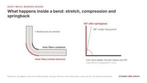
Press a sheet into a V-die and the cross-section does three things at once, none of them visible on the finished part. The outer surface of the bend is stretching — genuinely thinning, on a microscopic scale. The inner surface is going the other way, compressing, and if you have ever watched a flange wrinkle on thick soft aluminum you have seen compression with nowhere to go. And between those two zones runs the neutral axis, a plane that simply rotates in place, neither stretched nor squeezed. Because the outside grows, the part comes off the brake longer through the bend than any flat-line drawing predicts. Bend allowance math exists to swallow that growth back into the flat pattern; it is bookkeeping for physics that refuses to be ignored.
Then the punch comes up and the bend partially unwinds. Springback, everyone calls it — the elastic energy the metal stored on the way in, spent on the way out. Order 90° and measure 91.5° on the first article; that gap is not sloppiness, it is the material’s elastic half reclaiming ground from its plastic half. Strength makes it worse, big radii make it worse, and here is the part that surprises buyers: two brackets from the same batch of stainless can spring back differently if their hardness sits on opposite sides of the mill tolerance. Good shops know this and stop pretending the first number is the last — they trial-bend, measure, then tell the CNC to chase a 88° that relaxes into 90.
The third mechanism only arrives when someone pushes past the limit. Outside fibers at a tight radius stretch until they simply tear; the wall thins, microcracks link up, and the corner cracks, sometimes only noticed at inspection or in service. This — not any rulebook — is why the minimum bend radius exists.
Every fabrication shop’s capability page states some version of the same opening rule, STARWAY MFG GROUP’s included: keep the inside bend radius at or above the material thickness. Take it literally on 2 mm mild steel and you start at 2 mm. The rule is a thumb, not a law — grade and temper move it, mill grain direction moves it, and a bend running along the coil grain fails at radii that cross-grain bends shrug off. But designs that respect the rule do not crack at the corner, full stop. Designs built under it get a phone call during quoting instead of a cracked prototype in the mail.
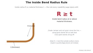
What follows from that one line surprises people the second time they read a drawing. Specifying a sharp 0.5 mm radius on 3 mm plate buys nobody anything: the shop either cracks the corner or forms it to whatever larger radius the die and metal agree on, and either way your drawing was fiction. Keep radii uniform across a part where you can — each radius change is another tooling shuffle, another pause mid-run, another chance for the second half of the batch to disagree with the first. And bring the grade into the conversation while you are at it. 5052 aluminum takes a tighter forming squeeze than hard temper alloys precisely because it was rolled to be shaped; the number next to “AL” on your material callout bends different, and cost a little less for the same reason.
Honest version of all this: when a corner matters, do not guess what the shop’s tooling will produce. One DFM question — what radius does this grade actually take on your brakes — costs the engineer ten minutes and saves a revision cycle nobody budgeted.
Radius settled, the remaining first-pass failures hide in details small enough to fit on one screenful of a drawing. Ours is the same list on every incoming review, and each entry earned its place by ruining somebody’s quarter.
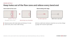
Holes that sit near bend lines are the classic. A circle punched into the flat pattern looks perfect until the bend arrives and drags the metal it lives in — the hole goes oval and walks a millimeter off its position, and the panel that “fit in CAD” meets the bracket at an angle. Clearance from the bend edge needs to grow as radius and thickness grow; the exact distance is shop arithmetic, not universal law. Where geometry forbids moving the hole, stop fighting: pierce or drill it after forming and let the ream round out what the bend distorted.
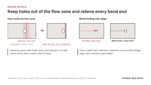
Bend relief notches are the detail junior engineers miss and shops quietly add anyway. A bend line that runs out into the middle of a flange edge has nowhere for the metal to go when it rotates, so the edge tears — a V-shaped rip climbing up from the bend termination. A notch at that termination is pennies of cutting time. Draw it; do not assume it appears.
Then there is the question nobody asks until a quote comes back with a red flag: how short can the flange be? The press brake needs to grip the flange beside the die opening, and a 5 mm flange formed over a 10 mm die is a negotiation, not a process. Five to eight times the material thickness is the friendly neighborhood; below that, expect pushback and longer setup.
Bend count is a budget item in disguise. Six bends means six setups or six flips, six datum transfers, six chances for cumulative error. Parts whose flanges avoid colliding with tooling mid-sequence form faster and hold angle better; a part designed so any bend order works is usually a part nobody checked.
Tolerance callouts deserve the same discipline as radii. A ±0.1° note on a hand-fed panel is science fiction — what modern CNC brakes deliver is roughly ±0.5° on ordinary bends, tightening to about ±0.25° when fixtures hold the part, with bend positions landing in the ±0.1 to 0.2 mm band. Call out what the machine can prove.
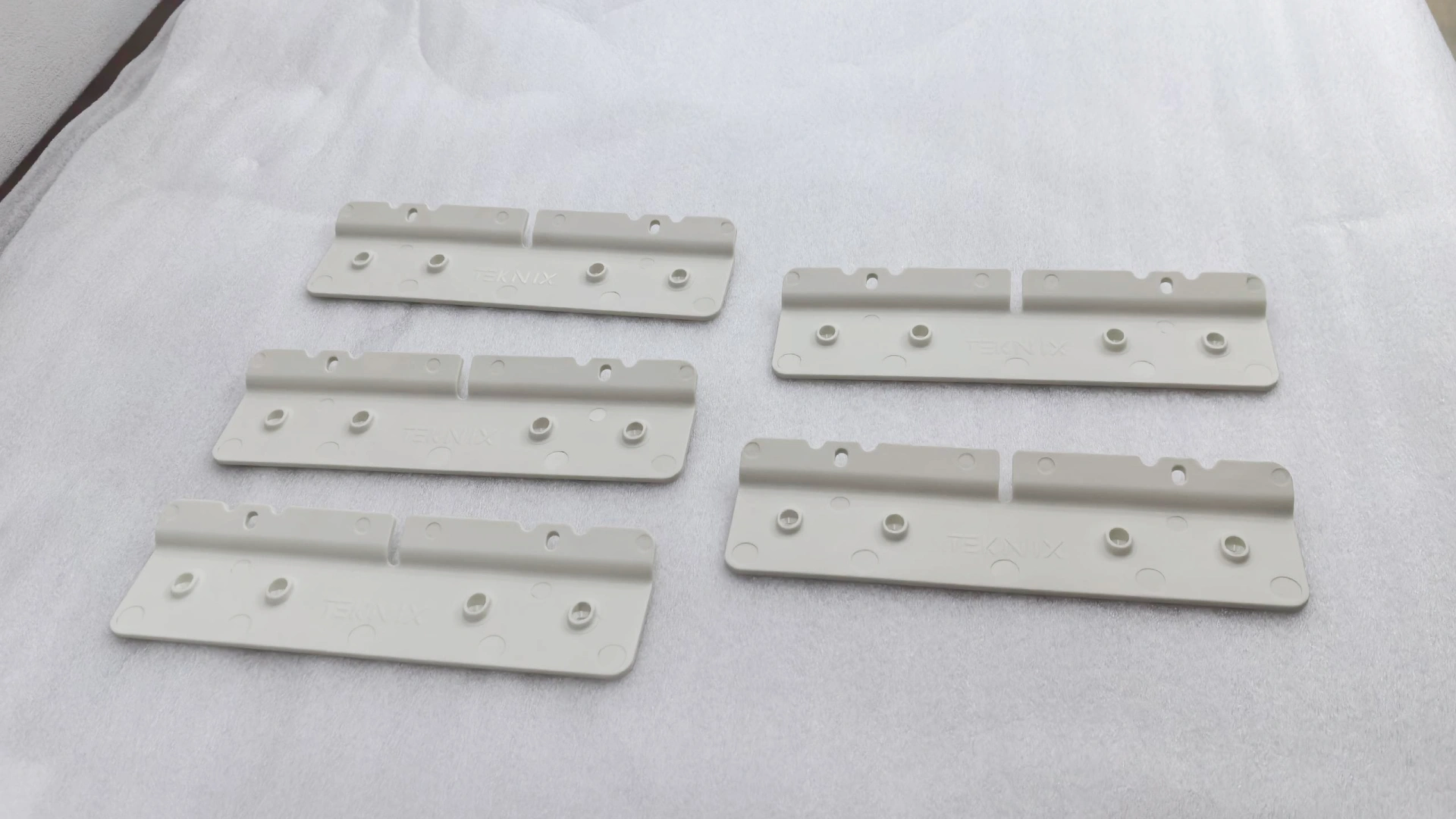
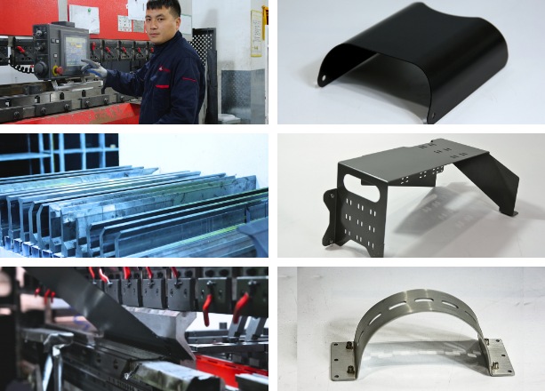
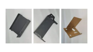
Last, grain. On cosmetic or loaded bends, a note saying “bend across grain” tells the mill, the slitter, and the shop the same truth your part needs; silence leaves it to whichever coil arrived first. A formed part silently testifies to all of these choices after the fact. Formed brackets like these show the checklist at work: relief at every bend end, holes outside the flow zone, and a first article checked against the drawing.
Press brake capacity is a three-way intersection, and a part can pass two of the three tests and still not fit any machine in the shop:
Tube work has its own envelope: STARWAY’s tube bending tops out at roughly 200 mm outer diameter by 5 mm wall, bend radii up to 250 mm and angles up to 190°, with wall thinning of 10–25% on tight-radius bends kept inside the process window.
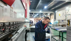
Ask any shop owner what is actually hard and the answer is rarely the first bend. Any competent operator makes one good bend before lunch. Four hundred bends, all within the same narrow band of angle and position, on a Friday night shift, with the same die that got warm at part two hundred — that is what your money buys. And it gets carried, or it doesn’t, by two things most buyers never look at.
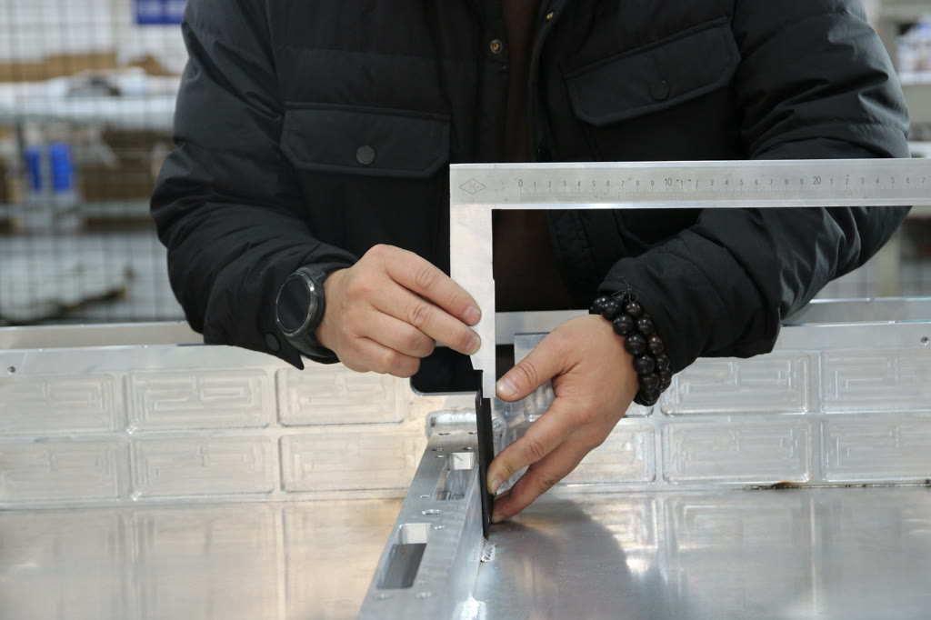
The first is the rhythm of checking. Good material never touches the laser before paperwork and chemistry get verified against the mill certificate; a coil that springs back a half-degree off spec is really a purchasing failure dressed up as a fabrication problem, and it is far cheaper to catch at the receiving dock than at final assembly. From there, a first article gets measured across the full dimensional set before anyone commits the rest of the order — and demand that this approval lands on your desk, not somewhere in the supplier’s inbox. Mid-run, checking should run on a clock, not on whoever feels like walking the floor. STARWAY pulls critical-dimension samples every two hours. Sounds pedantic until you realize what it means in practice: a tooling edge that is slowly dying shows up as a drifting trend line on Tuesday instead of as a pallet of finished scrap on Thursday.
The second is less visible: records. Push on any supplier with one specific question — “show me how you can tell me which machine bent which part on which shift” — and then quietly count the seconds. A shared spreadsheet plus ten years of institutional memory produces a shrug. An MES-driven production system, which is how STARWAY runs orders, produces fingerprints: the brake, the operator, the measured values, the drawing revision that was live at the time. So when angle starts wandering on part 1,800 of a 2,000-piece run, the hunt narrows to a shift, a tool change, maybe a material lot. Without it, the hunt narrows to nothing.
One more thing, and this one is yours, not the shop’s. Before parts ever ship, mark what “critical” means on your drawing. A first-article report that dutifully measures forty dimensions hands a decorative tab the same weight as the bore your assembly actually mates against, and the two numbers that matter get buried. Call out the bends and holes that carry function; let everything else sit as reference. Then disagreements on both sides of the quote shrink to three numbers instead of the entire page.
Formed almost never means only formed. A laser feeds the brake queue; welding locks formed assemblies into structures; and honestly, most of the ugly tolerance math hides in the seams between those steps — seams a single-shop drawing never shows you.
Laser first. It behaves once you know how it drifts: edges on sheet up to 3 mm hold around ±0.1 mm, above 3 mm you accept ±0.2 mm or worse, and the number that matters gets pinned down feature by feature during engineering review rather than promised in the brochure. Close-fit holes want flagging on the drawing plus drilling or reaming after cutting — trusting a thermal beam to hold a press-fit circle is how rework orders are born. And the ceilings? Material-dependent. Metal laser cutting at STARWAY runs carbon steel to 25 mm, stainless to 16 mm, aluminum to 12 mm. Why does that belong in a bending conversation? Because a heavy wall sitting beside your bend line doubles both bills at once: the tonnage you need and the cut-edge questions you inherit.
Welding then reaches into your nice formed angles and distorts them further — heat does not respect your drawdown notes. Joint design that ignores post-weld shrinkage produces assemblies that somebody trues, re-bends, or argues about, and the schedule usually pays first. Know the discipline split too. Production MIG on a frame and thin tight-tolerance TIG work on stainless detail are different bench crafts, however hard the marketing photos blur them. This is the exact seam where single-source fabrication earns its keep: one shop owning laser, brakes, and weld bays can name, per feature, which process owns which tolerance. Otherwise you pay that coordination tax in phone calls yourself.
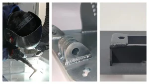
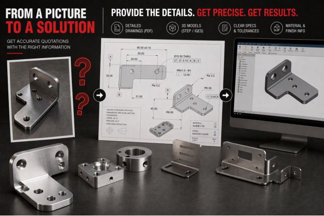
The cheapest lever in bending isn’t at the brake at all — it’s the RFQ package you send before anyone owns a machine hour. Engineering review begins there. Catch a 0.3 mm radius drawn on 4 mm plate at that stage and it costs a reviewer ten minutes; let it survive to the floor and it costs you a scrapped tooling round. So what actually belongs in the package? Geometry, both flat and formed — STEP or IGES preferably, DWG/DXF/PDF fine — because a reviewer cannot judge bend sequence from a flat pattern alone. Material grade and thickness, written per part, not implied by a title block someone forgot to update, and say what substitutions you’d accept. Then the functional bit: which bends and holes actually matter, and what the part mates against. Finishes, too, since a powder coat eats clearance you probably designed at bare sheet thickness. And honest annual volume with the release pattern, because fixture decisions built on a fantasy quantity get passed on to your unit price.
STARWAY’s engineers review drawings, tolerances, materials, and feasibility on every project before metal moves, prototype new designs in one to two weeks, and treat any material or thickness substitution as something to bring back for written approval. Shipping runs EXW, FOB, CIF, or DDP, tracked from the factory floor. If your current RFQ process is a zip file and a hope, the RFQ checklist for an accurate quote walks through what changes on the supplier’s side when the input is structured. For bending-specific review, the CNC bending capability page lists the full envelope — tonnages, lengths, thicknesses, angles — the team quotes against.
Q1: How far should a hole be from a bend line?
A1: Bigger than your drawing probably says. The honest rule is “outside the zone where metal actually moves,” and that zone stretches with both the inside radius and the thickness — a hole that behaved on last year’s 1 mm panel with a 1 mm radius can distort badly when the same design lands on 3 mm stock bent to 4 mm. Forget memorizing clearance tables; no two shops follow them the same way anyway. Do the arithmetic once with your fabricator per material family, then write the number into your own design standard so it stops being folklore. And if a feature genuinely cannot move out of the flow zone, move the operation instead. Drill after forming. One extra handling step, a perfectly round hole, no rework conversation.
Q2: Why does my 90° bend measure 91.5° and whose fault is it?
A2: Nobody’s, which is going to make this a short argument. The moment the punch retreats, elastic energy stored on the way in gets spent, and the bend relaxes a little — every sheet does it. High-strength steel and stainless do it harder than mild steel; a wide inside radius stores more of that springy strain than a tight one does. Shops counter it three ways: over-bend (shoot for 88° so the relaxed part settles at 90), coin the corner, or nudge the angle mid-run against measurements. Each of those counter-moves eats trial pieces and iteration time. Suspiciously fast online quotes are frequently fast because that labor got quietly deleted from the price sheet.
Q3: Can a press brake make a truly sharp corner?
A3: I’d reframe this one, because the corner you’re picturing doesn’t exist. What looks sharp is the die’s natural radius — usually somewhere near the material thickness whether you drew it or not — just small enough to fool the eye. Drawing “0” doesn’t buy sharpness; it buys a promise no shop intends to keep, and occasionally a junior engineer six months out tightens a working radius down toward that fiction. So call out the smallest radius your shop can prove it holds repeatably. Want the visual of a crisp line on a cover? A hem crease or a finish edge gives you that look without asking steel to fold like paper.
Q4: Should I bend with or against the mill grain?
A4: Across it, any time the bend matters. The mill rolls sheet, grain elongates along the rolling direction, and folding across that grain recruits the material’s real ductility. Fold with the grain instead and edges start cracking at radii that bent cleanly the other way — you’ll see it first on cosmetic panels and load-bearing flanges, and hardest on stainless at tight radius. Mills and slitters can cut coils to orient grain your way, sure, but only if the instruction survives every handoff from coil order to brake setup, and instructions living only in someone’s memory never survive. Put it on the drawing. A silent drawing is a grain-direction lottery.

This website uses cookies to provide you with a personalized browsing experience and analyze website traffic. By clicking "Accept", you agree to our use of cookies.



 Global