
Sheet Metal Fabrication Design Engineering Project management Assembly Packaging Rapid Prototyping Shipping & Delivery
CNC Machining Design Engineering Project management Assembly Packaging Rapid Prototyping Shipping & Delivery
Plastic Injection Molding Design Engineering Project management Assembly Packaging Rapid Prototyping Shipping & Delivery
Technical Guide | STARWAY MFG GROUP
By Alyssa / November 2026
Mostly for the OEM engineers, buyers and designers who have a part open in CAD and aren’t sure which machine it should go to.
Contents
Say a drawing comes in for a little 6061 housing (four M4 tapped holes, a pocket about 30 mm deep, one flat face that has to seal) and the buyer asks us for a turning quote, mainly because the bore in the middle is round. I understand why. But that bore is a single feature, and almost everything else on the part is cut on flat faces from three or four directions, so in my experience it belongs on a mill first. If you only remember one test from CNC milling vs. CNC turning, make it this one: look at which features actually drive the job, not at the one that catches your eye.
Now picture a 303 stainless shaft instead, with two diameters, a shoulder and a bore running down the axis. Nobody would argue about that one; it’s a lathe part. It stays a lathe part right up until somebody adds a cross hole or a keyway, at which point you’re deciding between a second setup on a machining center and a lathe that has live tooling on the turret.
Both processes are accurate, and I’d be suspicious of anyone who tells you one is always cheaper or always more precise. The route gets decided by the geometry, the datums, whether the tool can reach the feature, how many parts you need and (people forget this one) how the part is going to be inspected.
If the part is mostly flat faces, pockets and hole patterns (housings, plates, brackets), I’d start the conversation with milling. If it’s mostly concentric diameters, like shafts, bushings, sleeves or pins, start with turning. Parts that have a bit of both are where it gets interesting, and there it’s worth pricing two routes side by side: two separate operations, or a single mill-turn setup. Whichever one holds the critical features with fewer risky clampings is usually the right call.
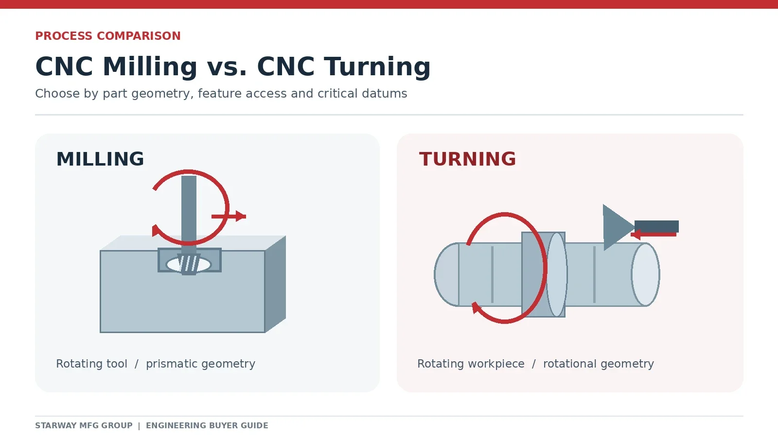
Figure 2. Choose by part geometry, feature access and critical datums.
On a CNC milling machine the cutter is what spins; the workpiece sits still in a vise or a dedicated fixture while the tool, the table, or both travel along the programmed axes. Plenty of brackets and housings never need more than three axes. Additional axes earn their keep when features are spread across several faces, or when a feature is tucked somewhere a straight tool can’t get to.
The number I always look at first is the setup count. Cutting the pocket might take ten minutes, but if there’s a hole square to the back face, that can mean flipping the part into a second fixture, and each re-clamp is another chance for the datums to wander by a few hundredths.
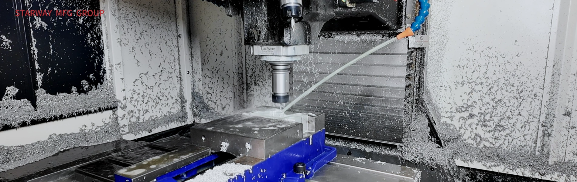
Figure 3. Face milling an aluminum block in a vise: the cutter turns, the part stays put.
CNC turning flips that arrangement around: the spindle spins the bar, and the tool moves along it or straight across it. That’s the reason outside diameters, shoulders, grooves, end faces and most bores come off a lathe so fast. A lot of modern turning centers have live tooling as well, though I wouldn’t take that for granted on any particular machine; it’s worth asking what the turret can really do before you plan around it.
On turned parts the thing that usually decides pass or fail is how well each feature sits on the datum axis, which the drawing will express as runout or position (ISO 1101). And a shaft that looks trivial on paper can turn into a headache if it’s long and skinny, since it bends away from the tool partway through the cut.
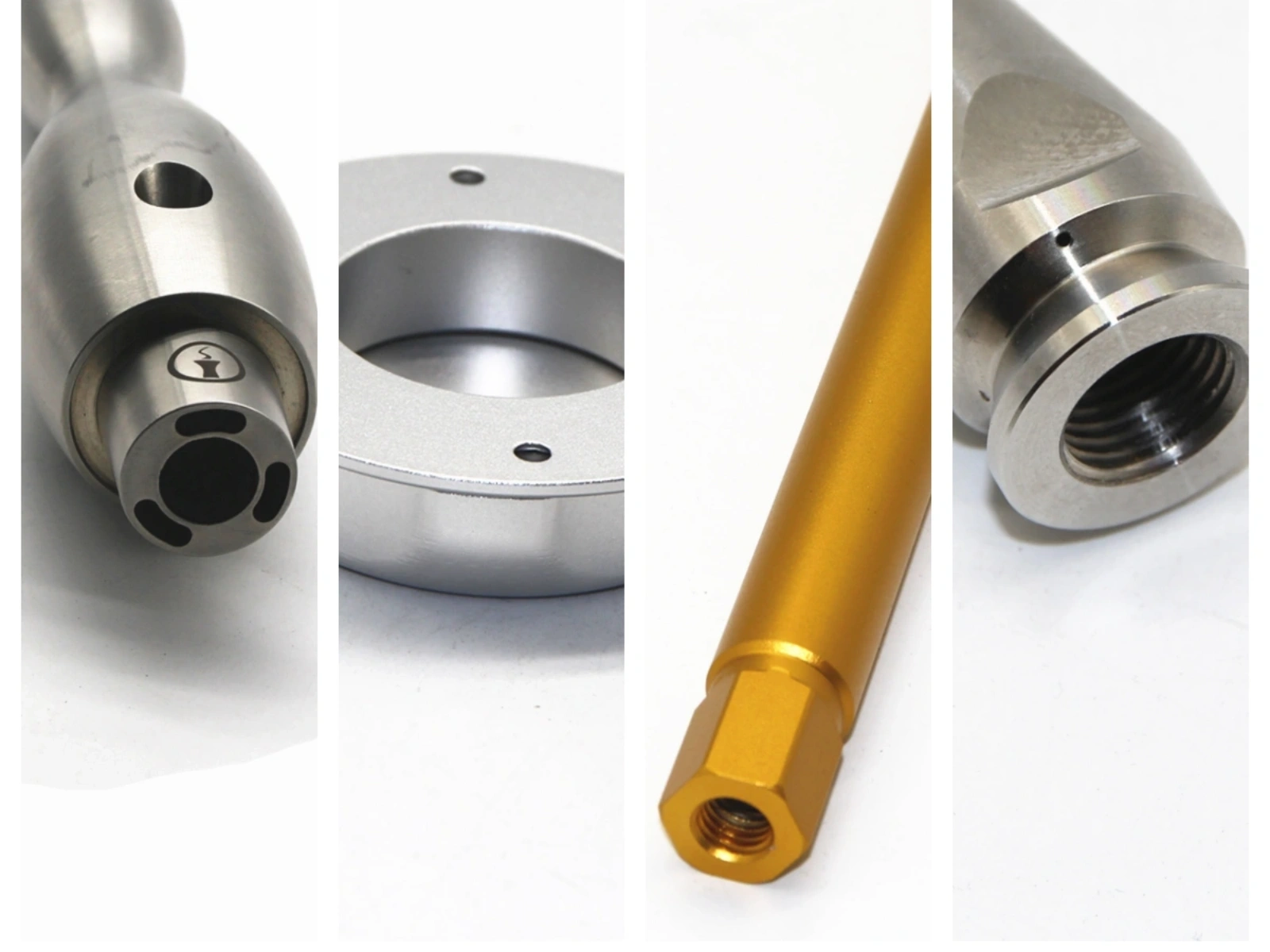
Figure 4. Typical turned parts: concentric diameters, bores, threads and end faces.
Having one round feature on it doesn’t make a part a turning job. A square housing with a precision bore is, nine times out of ten, still a milled part. The reverse happens too: a flange that starts life on a lathe can end up needing the mill once it picks up off-axis slots or a bolt circle that the lathe can’t finish at a price anyone would pay.
| Part / Feature | Usually Start With | Reason |
|---|---|---|
| Aluminum electronics housing | CNC milling | Pockets, flat sealing faces and multi-face holes |
| Steel shaft or spacer | CNC turning | Coaxial diameters, shoulders and end faces |
| Mounting bracket | CNC milling | Prismatic profile, slots and planar datums |
| Flanged sleeve with cross-holes | Turning + milling / live tooling | Rotational body plus off-axis features |
| Round plate with bolt pattern | Depends on tolerances and setup | Face/bore relationship versus hole access |
“Can your machines hold 0.01 mm?” is a question I hear a lot, and honestly it can’t be answered until you say which feature you mean. Measuring a short turned diameter and measuring a wide milled sealing face are two quite different problems, and material, feature size, temperature, tool wear and the way the part is clamped all move the result.
As a rough starting point in early RFQ discussions, people tend to talk about ±0.05–0.10 mm on ordinary milled dimensions and something like ±0.02–0.05 mm on turned diameters. Those are typical industry talking numbers, nothing more; they aren’t STARWAY guarantees and they certainly aren’t hard limits. Tighter is often doable, but only after an engineer has looked at the specific feature, the process, and how it’ll be measured.
| Milled Feature | Inspection Focus | Turned Feature | Inspection Focus |
|---|---|---|---|
| Sealing face | Flatness / surface texture | Bearing seat | Diameter / roundness |
| Hole pattern | Position to datums | Shaft shoulder | Face runout / length |
| Milled pocket | Wall thickness / depth | Axial bore | Size / axis relationship |
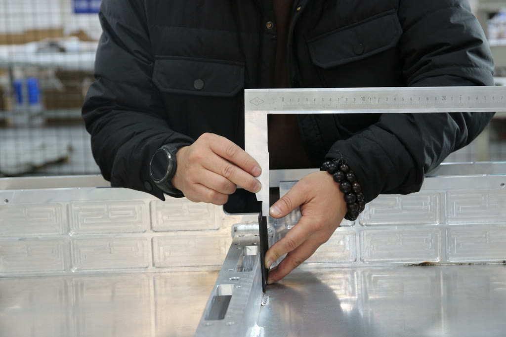
A useful first article report (see our quality control process) follows the functional datums on the drawing rather than just ticking through every dimension. When a shaft runs in a bearing, that bearing seat and its relationship to the other diameters is what I’d want to see measured. When a housing bolts to something else, the mounting pattern and the sealing face should be checked together, since that’s how the part will be used.
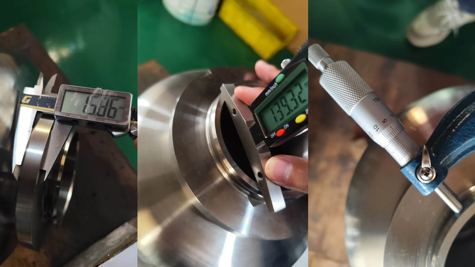
Figure 5. Checking a machined stainless steel flange with calipers and a micrometer.
On the milling side, cost climbs with deep narrow pockets, small internal corner radii, long-reach tools and parts that have to be re-oriented many times. Thin walls are another one; they can spring once the roughing is finished or the clamps are released. Opening a corner radius up by a millimetre or so will sometimes save a tool change and make the cut a lot more stable, although there are cases where it simply can’t change because the mating part dictates that shape.
Turning has a different set of traps. Long slender shafts chatter, or bend under the cutting load, and deep small-diameter bores make it hard to get the chips out. Narrow grooves can need special inserts, while a short grip length might mean soft jaws or a tailstock. If the drawing makes it clear which features matter, a decent shop can propose a sequence that actually works.
Stock size plays a part as well. A part that fits comfortably inside a standard bar diameter is often cheap to turn, whereas milling a large part out of thick plate turns a good share of expensive material into chips. Splitting it into several pieces avoids that waste but brings in joining and extra inspection, so there isn’t one answer that wins every time.
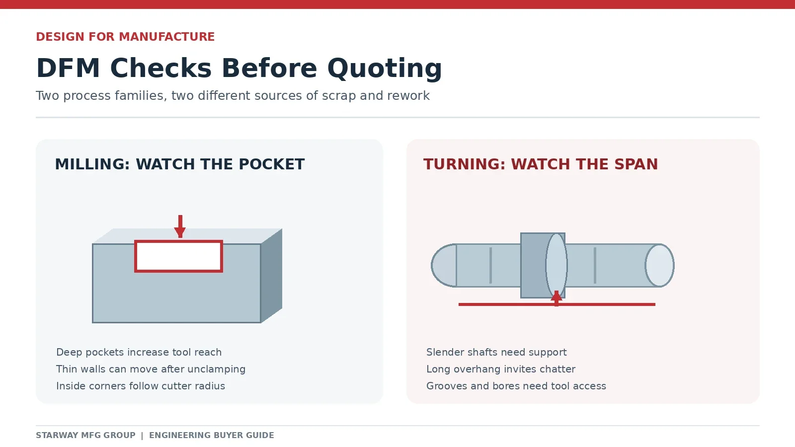
Figure 6. Typical DFM concerns: pocket depth and wall stiffness when milling, overhang when turning.
Here’s a hypothetical: a steel flange with a turned OD, a precision bore, four bolt holes and a slot on one side. The lathe handles the concentric features quickly, and the mill adds the holes and the slot afterwards. A mill-turn center could finish everything in one clamping, which sounds ideal, yet a conventional lathe followed by a machining center may still be cheaper, or may just have an open slot in the schedule this week.
When you weigh the two routes, look at setup time, fixture cost, how the features relate to each other, volume and inspection. Doing it in one setup is appealing, but it isn’t automatically the lowest cost, and on repeat orders a well-designed fixture often matters more than what kind of machine the part runs on.
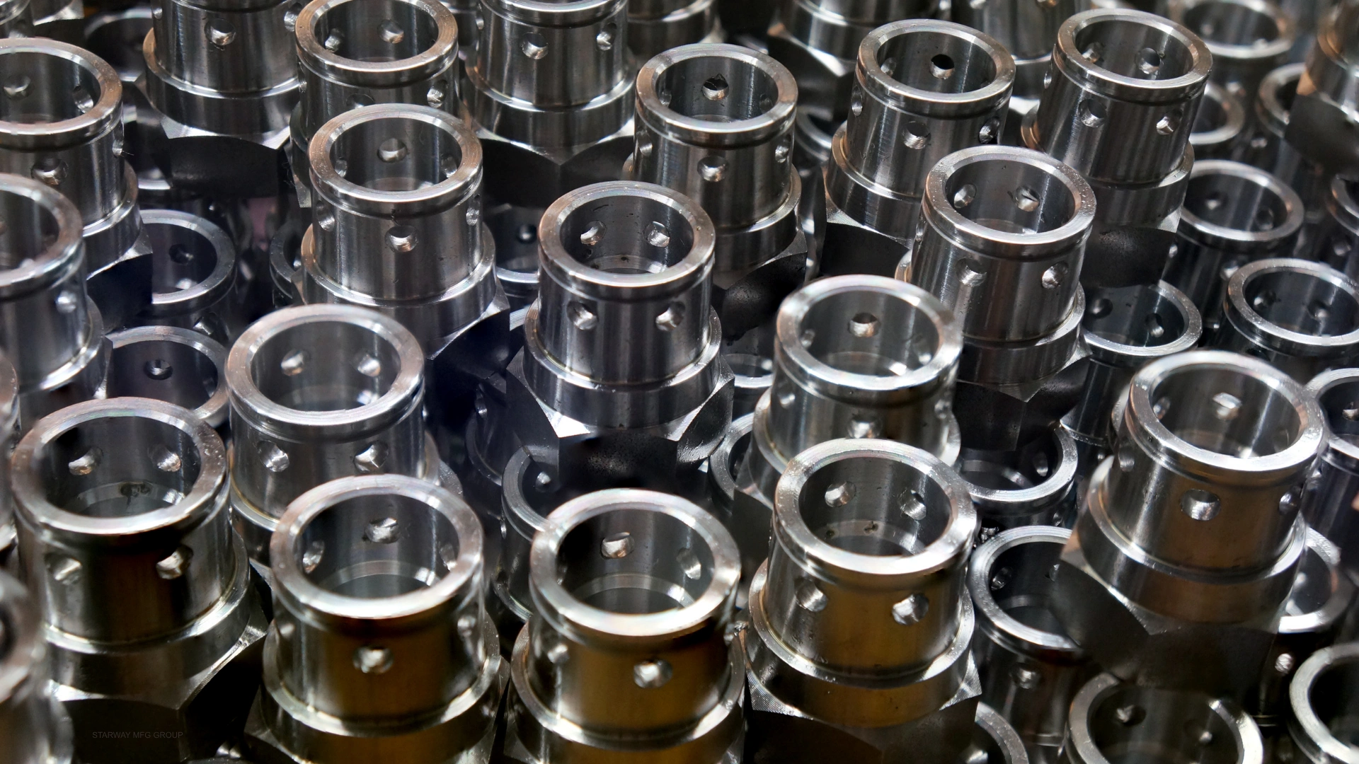
Figure 7. Turned fittings with cross-drilled holes: a typical turn-plus-mill part.
Cycle time is only part of what you pay for. Material yield, programming, workholding, setup, tooling, deburring, surface treatment, inspection and batch size all end up in the number, which is why five prototypes carry a much heavier share of setup cost than a repeat run of five hundred.
When the quotes come back, it’s worth checking line by line what each one actually covers: secondary operations, the surface finish you asked for, inspection of the critical features, packaging. A low unit price that quietly skips the second milling operation isn’t really comparable with the others.
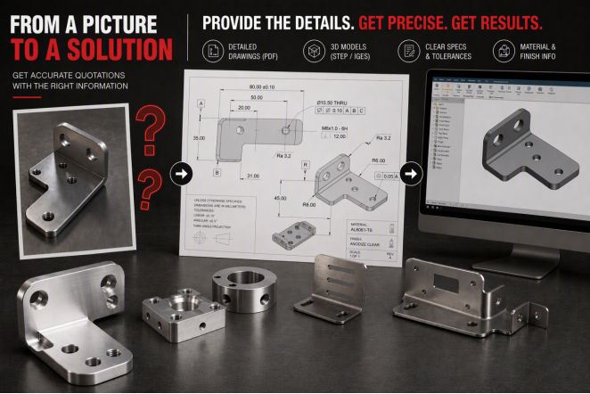
If you can, send a STEP model along with a controlled 2D drawing. Mark up the critical dimensions and datums, and include the material grade and temper, surface finish, quantity, the volume you expect on repeat orders and where the parts need to be delivered. Then ask the supplier to spell out the process route they’re planning, plus any DFM changes they’d suggest, before anything goes into production.
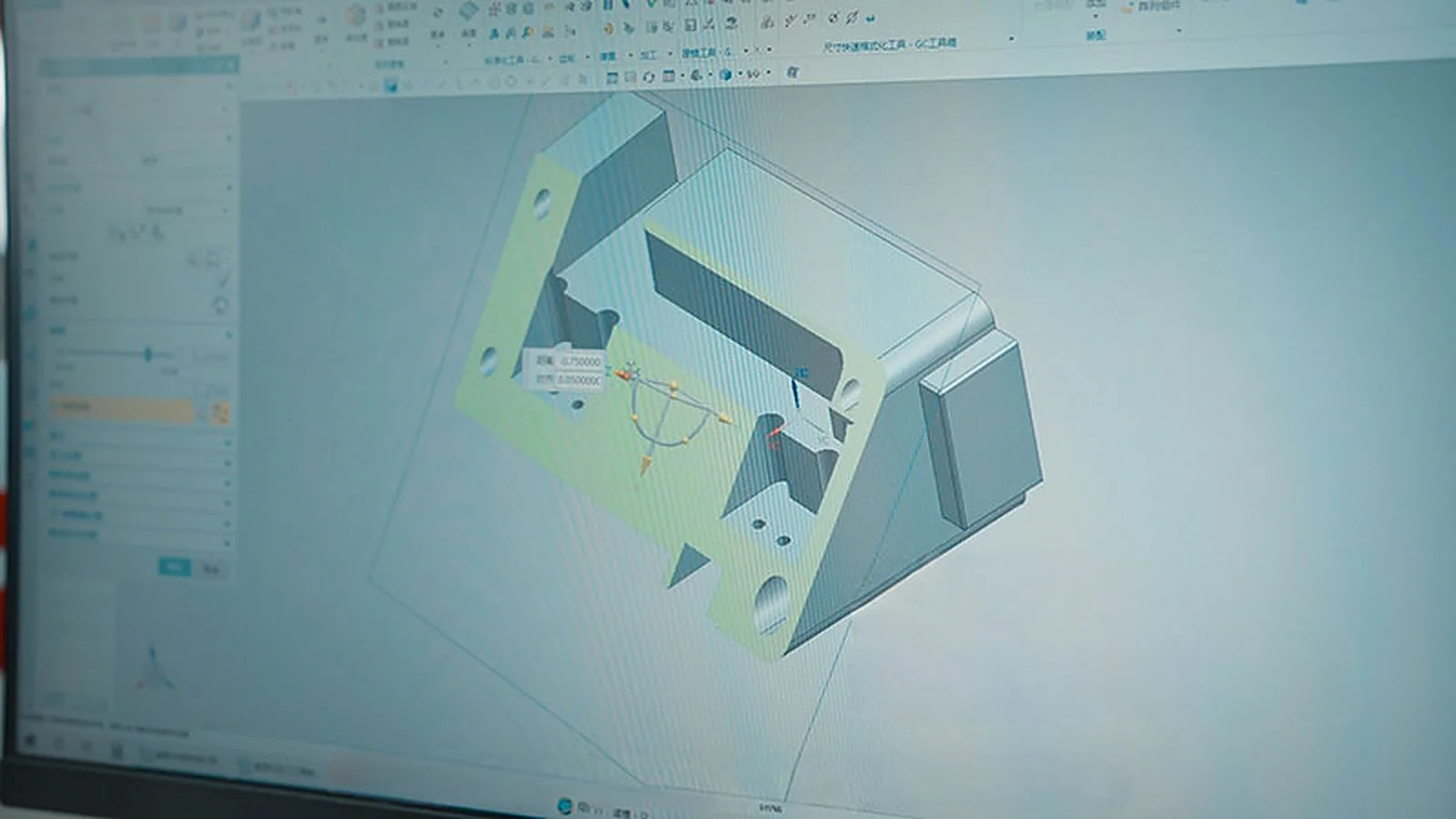
Figure 8. Reviewing the 3D model and key features before the quote is prepared.
STARWAY MFG GROUP does both CNC milling and CNC turning as part of its wider custom manufacturing work. For OEM projects we’d normally begin with a look at the drawing, confirming geometry, functional tolerances, material and expected quantity, and only then settle on the process sequence and the inspection plan with the customer.
If the part also involves sheet metal, surface treatment or assembly, those handoffs are worth talking through before anyone approves a quote. What you’re after is a part that can be made reliably and a supply route that repeats, which a process name printed on the purchase order doesn’t guarantee on its own.
Have a drawing ready?
Send your CAD files, the quantity and the features that can’t move.
Broadly, milling suits prismatic parts and turning suits round ones, while anything with a mix of features deserves a closer look. Go with the route that protects your critical datums, avoids setups you don’t need and gets you a quote whose scope is clearly written down; that’s a decision worth making before the first chip is cut.
Ready to compare routes for your part? Explore STARWAY’s CNC machining services.
Not as a rule. Accuracy depends on the specific feature, the tolerance, the material, the fixture and the inspection method, so compare those rather than the process names.
With milling the cutting tool rotates, whereas with turning it’s the workpiece that rotates while a fixed tool cuts it.
Turning is normally the first choice, since concentric diameters and shoulders are exactly what a lathe is built for.
Most turning centers can drill axial holes, and those with live tooling can often add some off-axis holes and slots as well, depending on how the machine is configured.
Yes, a mill can produce bores and other circular features, although a part that’s mostly round is usually cheaper to make on a lathe.
Parts whose shape comes mainly from flat faces, pockets and slots rather than round surfaces; housings and brackets are the classic examples.
It’s useful when a round part also carries cross-holes, slots or other milled details and you want to cut down the number of setups.
That depends on stock, programming, how complex the fixture is, the number of features and setup time, rather than on the machine type by itself.
It varies with the feature and the process, so agree on drawing-specific tolerances and how they’ll be inspected before you place the order.
Ideally a STEP model, a controlled 2D drawing, the material specification, quantity, finish and any critical functional requirements.

This website uses cookies to provide you with a personalized browsing experience and analyze website traffic. By clicking "Accept", you agree to our use of cookies.



 Global