
Sheet Metal Fabrication Design Engineering Project management Assembly Packaging Rapid Prototyping Shipping & Delivery
CNC Machining Design Engineering Project management Assembly Packaging Rapid Prototyping Shipping & Delivery
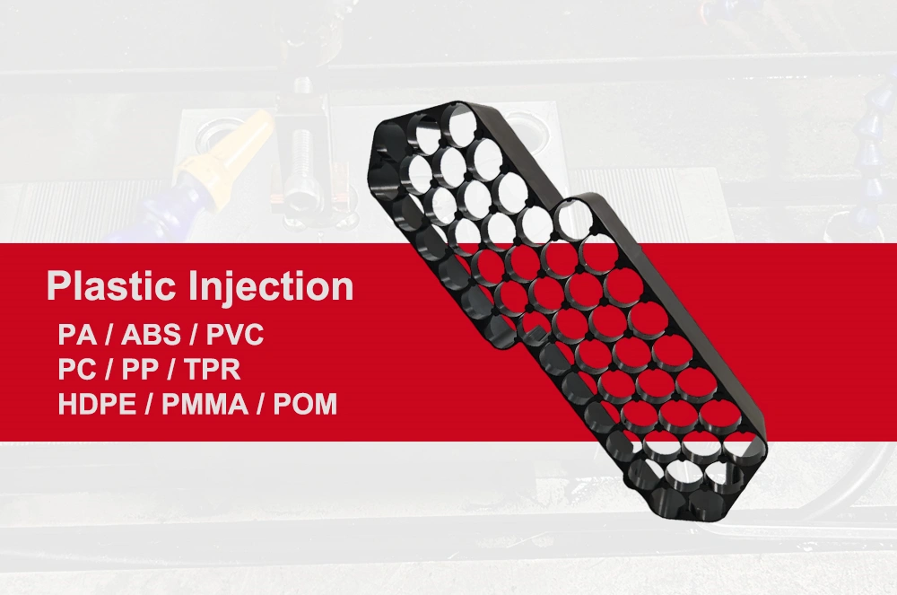
Plastic Injection Molding Design Engineering Project management Assembly Packaging Rapid Prototyping Shipping & Delivery
TECHNICAL GUIDE | STARWAY MFG GROUP
By STARWAY MFG GROUP
Design for reliable filling, cooling and ejection before you commit to tooling.
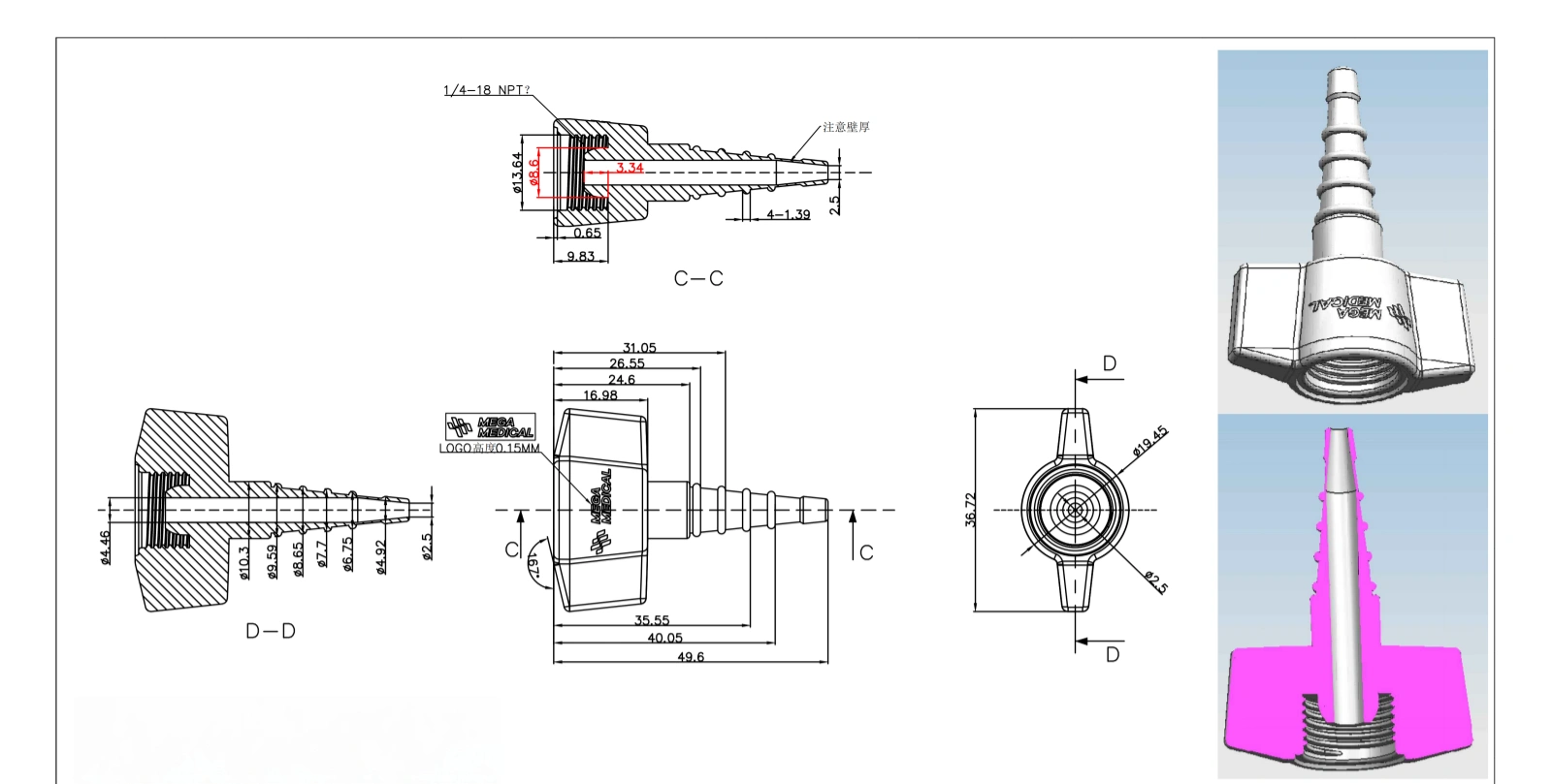
Connector drawing showing the dimensions and features to review before tooling.
A part can look perfectly reasonable in CAD and still be expensive to mold. A deep pocket traps the core. A snap hook points the wrong way for ejection. Or a thick mounting boss leaves a visible sink mark on the opposite face. These are not unusual failures. They are the sort of details that become costly when the tool is already being cut.
Designing a plastic part for injection molding means making those choices before the mold layout. The part has to meet its functional requirements, but it also has to fill, cool, release from the tool and hold the dimensions that matter. A feature that is easy to 3D print may need a different shape once it moves into an injection mold.
This guide focuses on practical DFM injection molding checks: wall thickness, draft angle, ribs, bosses, undercuts, gates, material behavior and inspection. It is meant for teams preparing a drawing or an RFQ, not as a substitute for a resin-specific tooling review. For the broader sequence from mold construction to production approval, see our plastic injection molding process guide.
Start with what the plastic component must survive. Does it carry a screw load? Seal against a gasket? Snap into another part? Sit outdoors? The answer affects the resin, the geometry and the acceptance criteria. A housing that only locates a circuit board is not designed the same way as a bracket exposed to vibration or a cover that is removed every week.
Separate the requirements into three groups: functional interfaces, cosmetic surfaces and process constraints. Mark the holes, clips, sealing faces and datums that must fit other parts. Then identify the surfaces a customer will actually see. If the part has a visible A-surface, gate marks, ejector marks and weld lines need an agreed location rather than an argument after the first samples arrive.
Before asking for a tool quote, send the 3D model, a controlled 2D drawing, expected annual volume, preferred resin or performance requirements, finish expectations and any applicable testing standard. A supplier can make useful DFM comments from that package. “Make it look like the prototype” is not a measurable specification.
Uneven wall thickness is one of the fastest ways to create molding trouble. A heavy section cools more slowly than the surrounding wall; that difference can pull material inward and leave sink marks or internal voids. An abrupt transition can also change flow behavior and contribute to warpage. The aim is not to make every wall thin. It is to use a thickness the selected resin can fill reliably and keep transitions gradual.
For many unfilled commodity thermoplastics, roughly 1.5–3.0 mm is a useful early design discussion range, not a universal rule. A small PP living-hinge part, a PC enclosure and a glass-filled PA bracket will not share the same optimum thickness. Flow length, gate position, cosmetic finish and structural requirements may move the target considerably. Check the resin supplier’s recommendations before freezing the nominal wall.
Suppose a 2.0 mm housing wall meets the stiffness requirement except around one mounting point. Making the whole corner 5 mm thick is likely to create a cooling imbalance. A ribbed support or a cored-out boss may deliver the needed stiffness with less mass. The toolmaker should still check whether the core can be machined, vented and cooled.
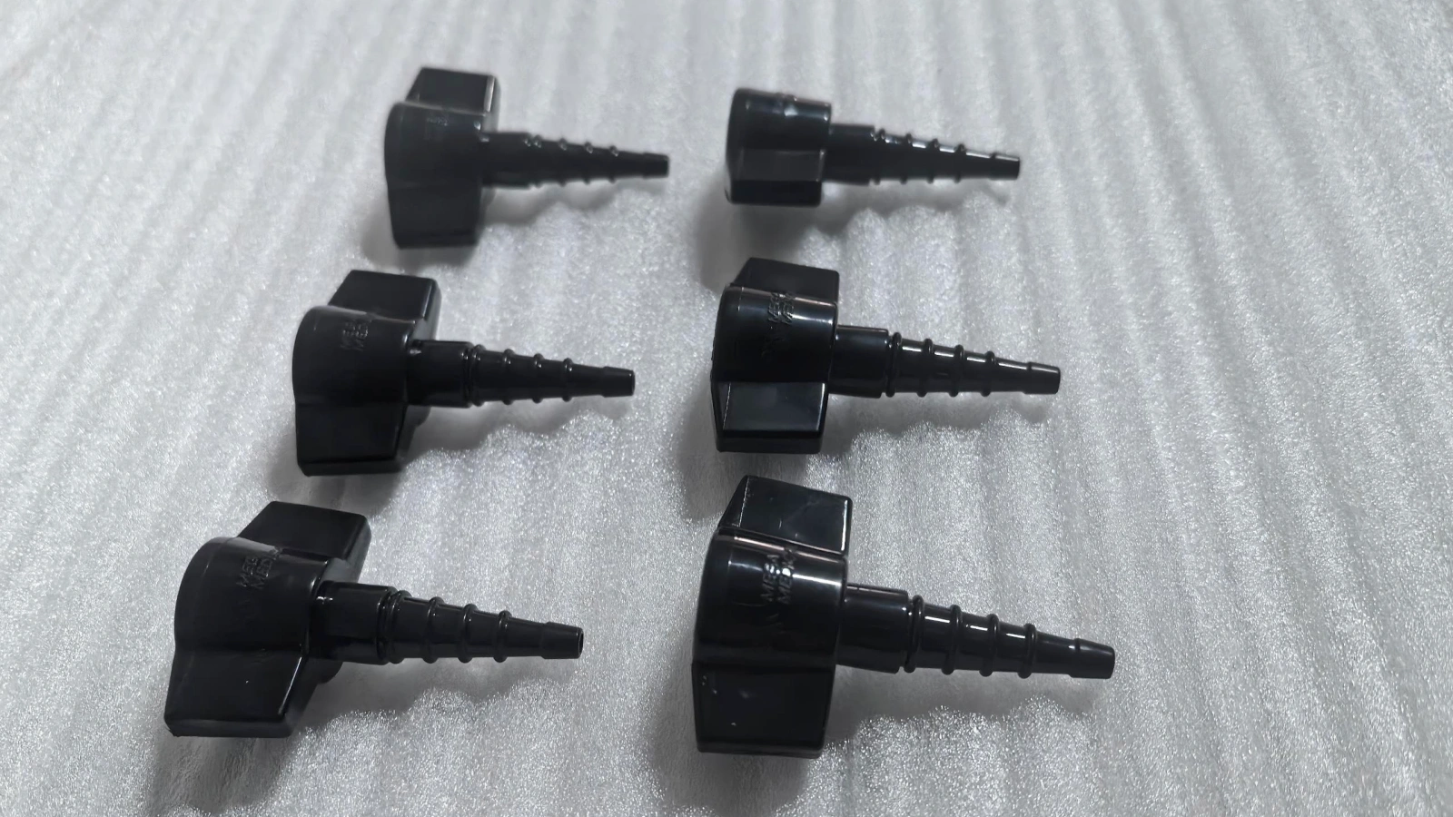
Molded connectors for reviewing wall sections and potential sink marks.
A vertical wall that looks clean on the screen may scrape against the cavity as the molded part is ejected. Draft reduces that contact. It is especially important on deep walls, textured surfaces and features that shrink tightly around a core.
A starting discussion for many smooth thermoplastic walls is about 1–2° of draft per side, but that is not a guarantee of adequate release. Deep cores, textured finishes and difficult resin/tool combinations may need more. The appropriate angle depends on the draw depth, material shrinkage, tool finish and where the part grips the steel. Specify the pull direction first; then measure draft relative to that direction.
Do not add draft blindly to a functional fit. A connector opening or sliding guide may need controlled geometry. That can mean relocating the parting line, changing the orientation, or machining a secondary feature. The correct choice depends on how the part is assembled and measured.
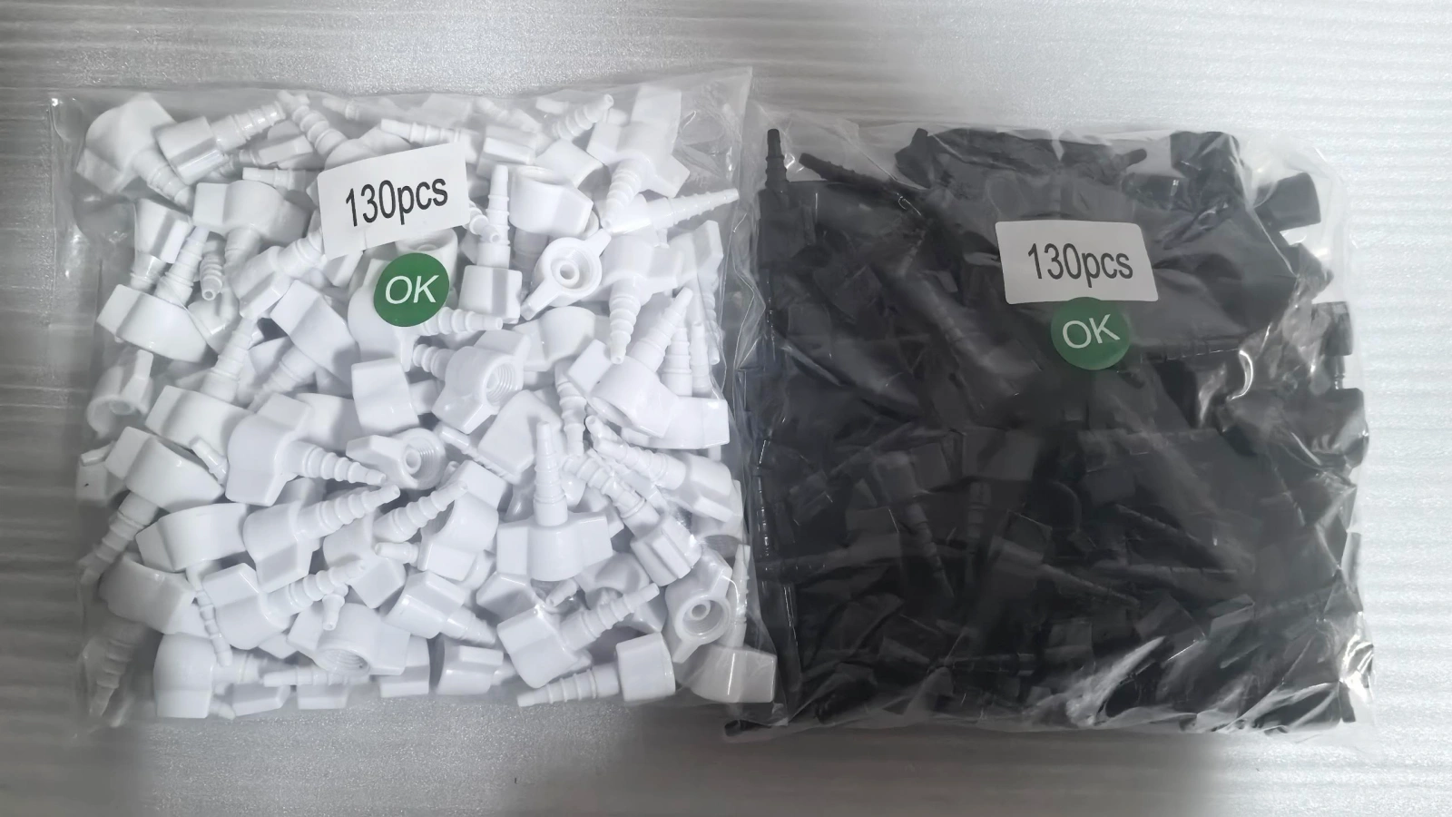
Production parts for reviewing draft, pull direction and ejection.
Ribs add stiffness without making the entire wall thick. As an initial DFM check, designers often start a rib near 50–60% of the adjacent nominal wall thickness, then adjust for resin, flow and appearance. Thick ribs on a cosmetic face can print through as sink. Extremely tall, thin ribs can be hard to fill or eject. A small radius at the rib base helps avoid a sharp stress concentration, but oversized radii can create a local thick spot.
Screw bosses need the same attention. Core the boss where possible, support it with ribs rather than a massive solid base, and leave enough material for the intended screw or insert. A rough starting boss wall may be around 60–80% of the adjacent wall, subject to fastener type and resin. The supplier should verify pilot-hole geometry against the screw manufacturer’s recommendations and the expected torque or pull-out requirement.
Rounded internal corners generally reduce stress concentration and improve flow compared with sharp corners. They also make the cavity easier to machine. The outside radius should follow the inside radius so the wall does not become unnecessarily thick at the turn.
Snap-fits deserve a separate review. A hook that works once in a printed prototype may fail after repeated flexing in a molded resin. Check allowable strain, root radius, assembly force, creep under sustained load and whether the hook creates an undercut. An accessible cantilever can sometimes be redesigned to release with the main mold opening, avoiding a side action.
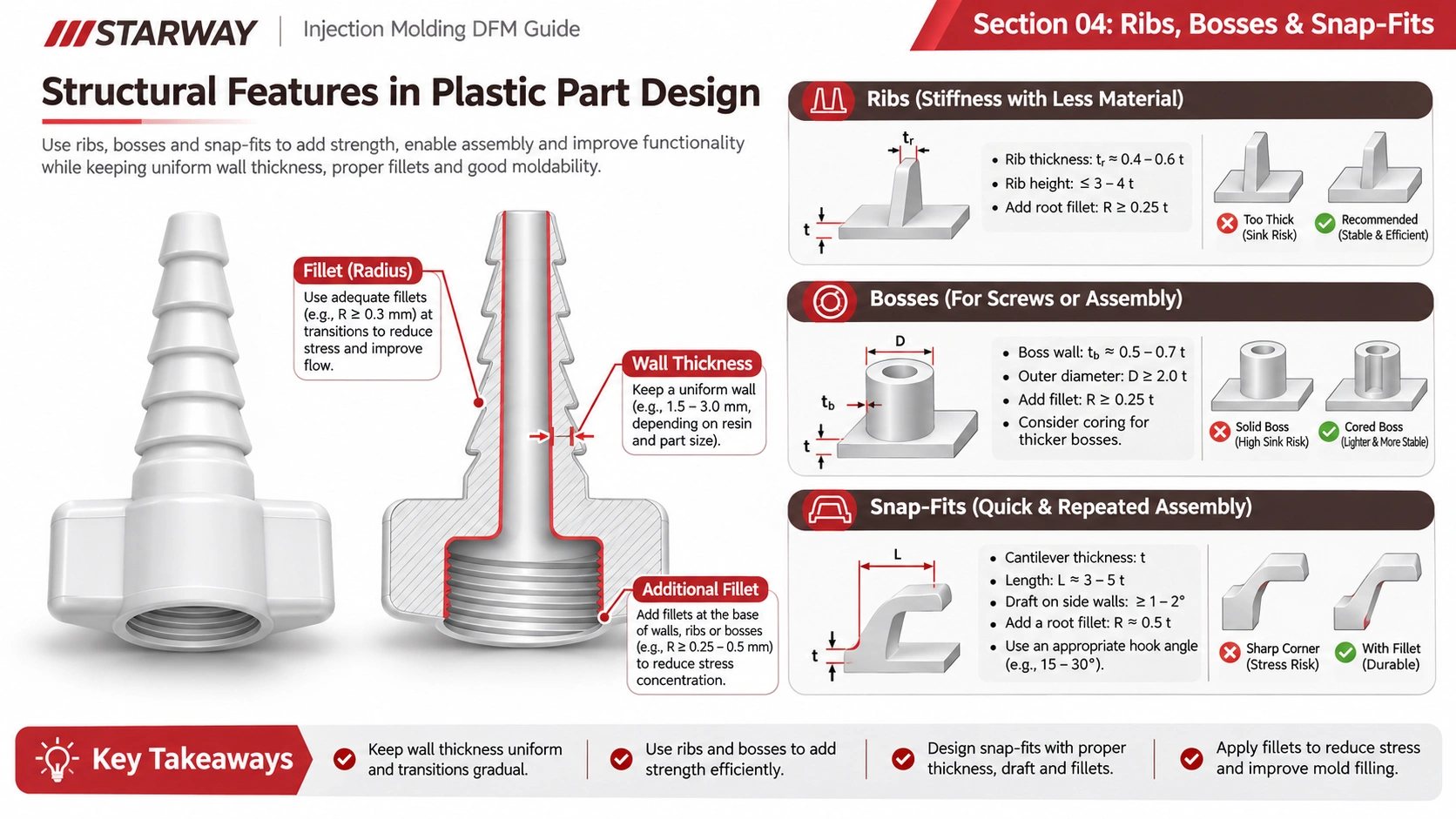
Ribs, bosses, radii and snap-fits in plastic part design.
A mold must open and release the component. That simple requirement should influence the design long before the steel layout begins. Holes and clips aligned with the opening direction are usually easier to tool than side holes, reverse hooks and enclosed undercuts.
A side-action slide, lifter or collapsible core can make an otherwise impossible feature moldable. It also adds moving components, maintenance and tool-build complexity. Sometimes that cost is justified. Sometimes moving a hole, changing a clip or splitting one part into two components produces a better result. Ask the mold designer to show the proposed opening direction and any required side actions on the DFM drawing.
The parting line is not just a tooling detail. It can affect flash risk, cosmetic appearance and the location of dimensional variation. Agree where it may appear, especially on sealing surfaces and visible edges. If a critical face crosses the parting line, ask how the supplier intends to control it.
The gate is where molten plastic enters the cavity. Its location affects filling balance, pressure loss, packing, visible marks and sometimes the orientation of glass fibers. A gate placed only for easy trimming may create a weld line exactly where a screw boss needs strength.
For an enclosure with two openings, the flow fronts may split around the openings and meet on the far side. That meeting region can form a weld or knit line. It may be acceptable on a low-stress wall and unacceptable across a loaded latch. Ask the tooling team to mark likely weld-line areas and explain whether gate position, wall changes or venting can improve the result.
Air also needs a path out. Poor venting can contribute to burn marks, short shots or inconsistent filling. Vent design is tool- and material-specific; it should not be reduced to a single generic vent dimension in the part drawing. Flow analysis can help on demanding geometries, but a simulation is only as useful as its resin data, boundary conditions and later trial validation.
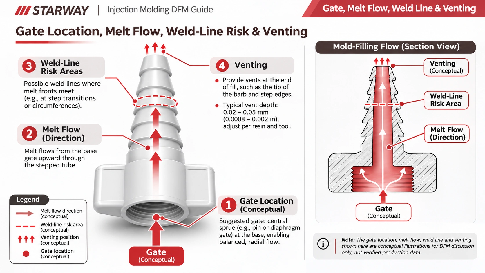
Gate location, melt flow, weld-line risk and venting.
A nominally identical design can behave differently in ABS, PC/ABS, PP, POM or glass-filled nylon. Shrinkage, stiffness, impact resistance, moisture uptake, chemical resistance and flow behavior all matter. For example, a glass-filled resin may offer higher stiffness but can show anisotropic shrinkage and a different surface appearance. PA can absorb moisture, affecting dimensions and mechanical behavior after molding.
Avoid approving a resin solely because its datasheet lists a high tensile strength. Look at the actual service temperature, impact exposure, chemical contact, UV requirements, flammability specification and whether the part must be painted, welded or bonded. Confirm the exact commercial grade, not only the polymer family.
| Material family | Often selected for | DFM question to resolve |
|---|---|---|
| ABS / PC-ABS | Housings, covers, appearance and impact balance | What finish, impact requirement and gate location are needed? |
| PP | Lightweight parts, chemical resistance, flexible features | How will shrinkage, stiffness and long-term creep be managed? |
| POM | Low-friction mechanisms and dimensionally stable functional features | Is the part compatible with the assembly, chemical environment and tool design? |
| PA / glass-filled PA | Loaded brackets, structural components | What moisture conditioning, fiber orientation and warpage risks apply? |
| PC | Tough, heat-resistant or transparent applications | Are drying, stress, thickness and cosmetic requirements realistic? |
A plastic part does not come out of the tool at exactly the cavity dimensions. It shrinks as it cools, and the amount is affected by resin grade, fiber content, flow direction, wall thickness, packing and tool temperature. Shrinkage values in a datasheet are useful starting information; they are not a substitute for trial parts.
Warpage is a shape problem, not merely a size problem. A flat cover can meet several local dimensions yet rock on the mating housing. Uneven cooling, asymmetric ribs and directional shrinkage can all contribute. Identify the functional datums and measure the assembled condition where that is what matters.
Avoid placing tight tolerances on every feature. Specify the dimensions that affect fit, sealing, fastener engagement and function; use a suitable general tolerance framework for the rest. ISO 20457 may be relevant for molded plastic parts, but any standard and tolerance class must be agreed for the actual design and process. Critical dimensions may need a measurement plan that states conditioning, temperature, datum setup and inspection method.
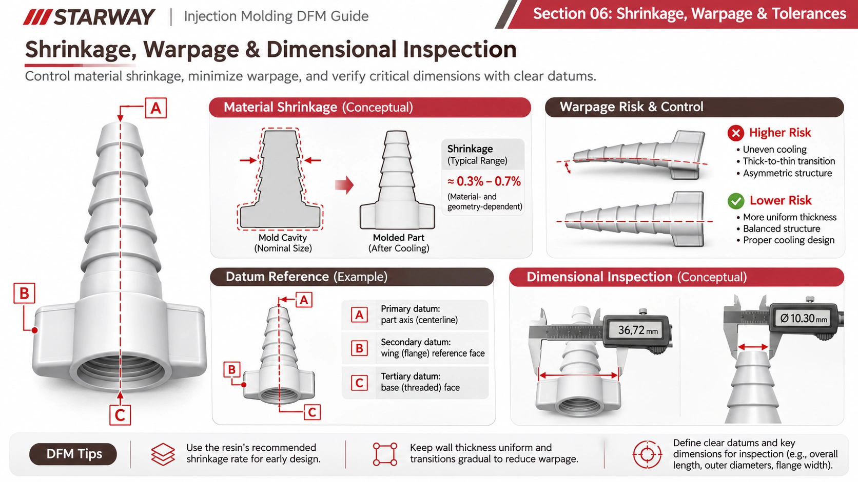
Shrinkage, warpage and dimensional inspection points.
A mold quote should describe more than a tool price. Ask about cavity count, tool steel, expected production volume, gate type, slides or lifters, cooling approach, maintenance and ownership. A low initial tool cost can be offset by longer cycles, higher scrap or difficult servicing. Equally, an elaborate multi-cavity tool may not be justified for a product whose design is still changing.
Prototype samples should be checked against the intended production process. A machined or 3D-printed prototype can confirm geometry and assembly access, but it does not prove the molded part will shrink, warp or perform in the same way. During T0/T1 trials, document defects and dimensional findings, agree changes and control the revision before another trial.
Before approving production, review the sample under realistic conditions: mating components installed, fasteners tightened, clips cycled and cosmetic surfaces inspected under agreed lighting. Record critical dimensions, material grade, color and finish. A first article inspection is most useful when it tests the features the product depends on.
A good DFM review turns an attractive CAD model into a buildable part. Use the questions below before releasing drawings to a plastic injection molding manufacturer.
| Review item | What to confirm before tooling |
|---|---|
| Function & interfaces | Critical datums, assembly loads, sealing faces and appearance zones identified |
| Nominal wall | Reasonably uniform sections and gradual thickness transitions |
| Draft & ejection | Pull direction, draft, core grip and ejector-safe surfaces agreed |
| Ribs & bosses | Cored sections, local thickness, screw type and expected loading reviewed |
| Undercuts | Slides/lifters identified, or feature simplified where practical |
| Gate & flow | Gate vestige, weld-line risk, venting and cosmetic restrictions discussed |
| Material | Exact resin grade, color, additives, shrinkage and testing requirements specified |
| Quality & RFQ | Drawing revision, inspection plan, annual volume and sample approval route defined |
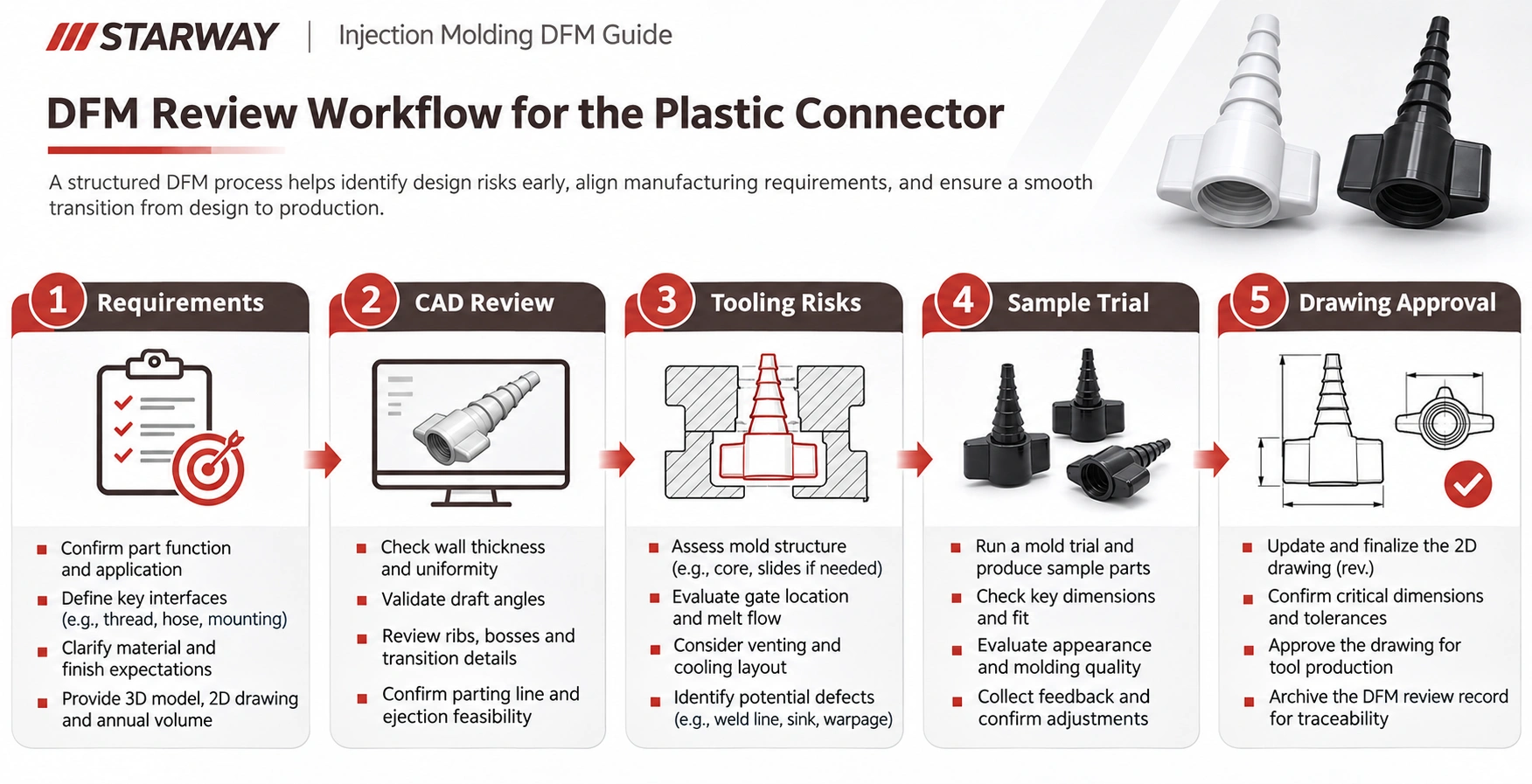
STARWAY’s plastic connector DFM workflow from design review to sampling.
At STARWAY MFG GROUP, the useful starting point is the drawing and the intended application. A review of wall thickness, draft, parting line, undercuts and critical interfaces can identify decisions that are easier to make before tooling than after the first trial. The company’s mold design and tooling capability and plastic injection molding service are relevant when the project moves from design review into toolmaking and production.
For a new OEM component, send the STEP model and controlled drawing together with resin requirements, quantity, finish, assembly information and any functional tests. If you are comparing a printed prototype with a molded production part, flag the features that must remain unchanged. The goal is to agree a manufacturable design and a sensible validation plan before the mold is released.
Ready for a DFM review?
Send your drawing, material requirements and target quantity.
Design for manufacturing (DFM) is the review of part geometry, material and functional requirements against molding and tooling constraints. It identifies problems such as insufficient draft, thick sections, difficult undercuts and risky gate locations before the mold is built.
There is no universal number. Many unfilled commodity thermoplastics begin with a discussion around 1.5–3.0 mm, but resin grade, flow length, geometry and structural requirements determine the appropriate wall. Uniformity and transitions matter as much as the nominal value.
About 1–2° per side is a common starting discussion for many smooth walls. Deep features, textures and difficult ejection may require more. Confirm the draw direction and review the draft with the toolmaker.
A thick region can cool and contract differently from the adjacent wall, pulling the surface inward. Heavy bosses, thick ribs and abrupt wall transitions are frequent contributors. Coring and more balanced wall design may help.
A common early guideline is roughly 50–60% of the adjacent nominal wall, adjusted for resin, height, flow and cosmetic requirements. Rib geometry should be reviewed rather than treated as a fixed universal ratio.
Often, yes. Reorienting a hole, modifying a snap feature or changing the parting line can eliminate some undercuts. Other features genuinely require slides or lifters. The choice depends on function and tooling economics.
The gate should support filling and packing while keeping vestiges and weld lines away from critical cosmetic or structural areas. Its position depends on geometry, resin, cavity layout and mold design.
They depend on resin, geometry, part size, tool quality, process control and inspection conditions. Specify functional datums and critical dimensions; agree general tolerance requirements with the manufacturer instead of applying the tightest value everywhere.
Not necessarily. Printing and molding can produce different material properties, layer structure, shrinkage and surface finish. Use printing to validate fit and design concepts, then confirm performance with molded samples.
Provide a 3D CAD model, controlled 2D drawing, resin and color requirements, expected volume, cosmetic zones, critical tolerances, assembly information and relevant testing or compliance requirements.
The best plastic part is not necessarily the one with the fewest features. It is the one whose geometry, material and tooling plan work together. Check wall thickness, draft, ribs, bosses, undercuts and gate locations before steel is cut. Then use molded samples to confirm the assumptions. That approach usually gives engineering and purchasing teams a clearer basis for approving the design and managing production risk.

This website uses cookies to provide you with a personalized browsing experience and analyze website traffic. By clicking "Accept", you agree to our use of cookies.



 Global