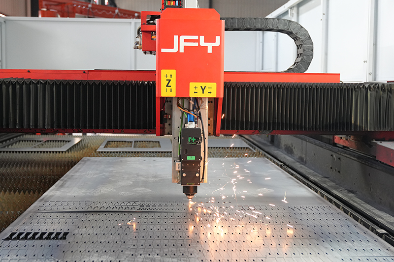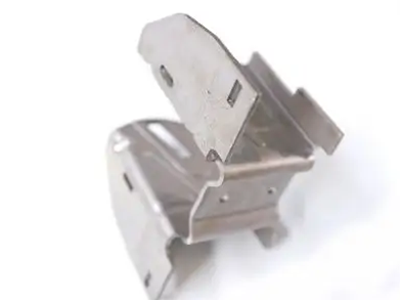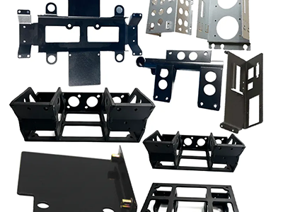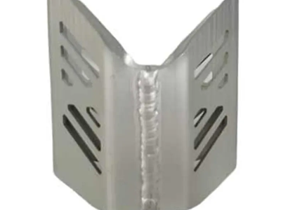

Sheet Metal Fabrication Design Engineering Project management Assembly Rapid Prototyping Packaging Shipping & Delivery
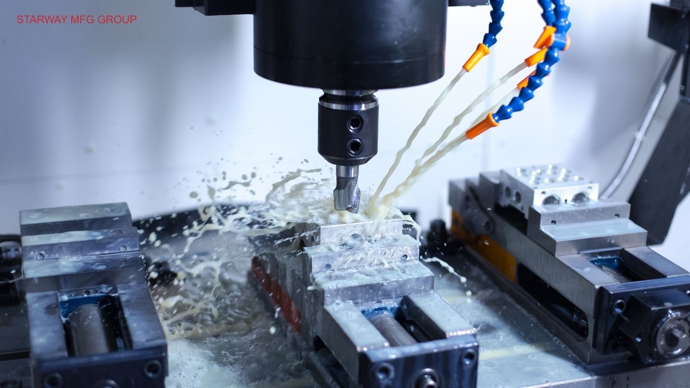
CNC Machining Design Engineering Project management Assembly Rapid Prototyping Packaging Shipping & Delivery
Plastic Injection Molding Design Engineering Project management Assembly Rapid Prototyping Packaging Shipping & Delivery
By Alyssa /
Plastic Injection Molding is one of the most widely used manufacturing processes for producing high-volume, repeatable, and cost-efficient plastic parts. For engineers, procurement managers, and product designers, the challenge is rarely only about “making a plastic part.” The real challenge is choosing the right resin, designing the right mold, controlling tolerances, reducing defects, and finding a manufacturing partner who can support the project from early-stage design validation to stable production.
A well-designed injection molded part can deliver excellent strength-to-weight ratio, consistent surface quality, complex geometry, and competitive unit cost. However, a poorly planned project can quickly become expensive. Mold rework, sink marks, warping, flash, short shots, unstable cycle time, wrong gate location, or material shrinkage problems can delay the entire product launch.
For global OEMs in Europe, Australia, and North America, supplier selection is also a strategic decision. Buyers need more than basic injection molding services. They need an engineering-driven manufacturer that understands DFM, mold flow, tooling design, polymer behavior, quality control, assembly requirements, packaging, and international delivery expectations.
This guide explains what plastic injection molding is, how the injection molding process works step by step, what materials are commonly used, how to evaluate injection molding cost, and how to choose a reliable plastic injection molding manufacturing partner. It also compares injection molding vs 3D printing, prototype injection molding vs production tooling, and different molding methods such as overmolding, insert molding, and 2-shot molding.
As a Chinese contract manufacturer serving global OEM customers, STARWAY MFG GROUP provides custom injection molding, mold tooling design, CNC machining, sheet metal fabrication, assembly, and quality inspection services under one manufacturing system. This makes it easier for customers to manage multi-process projects, especially when a product includes molded plastic housings, metal brackets, machined inserts, fasteners, and final assembly.
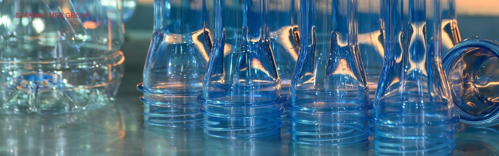
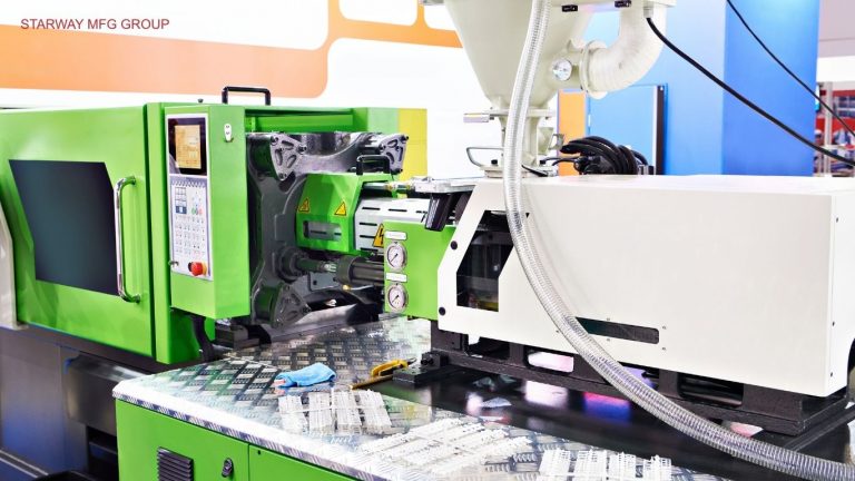
Plastic Injection Molding is a manufacturing process that produces plastic parts by melting thermoplastic resin and injecting it under pressure into a mold cavity. Once the molten polymer fills the cavity, it cools and solidifies into the final part shape. The mold then opens, ejector pins push the part out, and the cycle repeats.
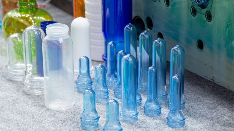
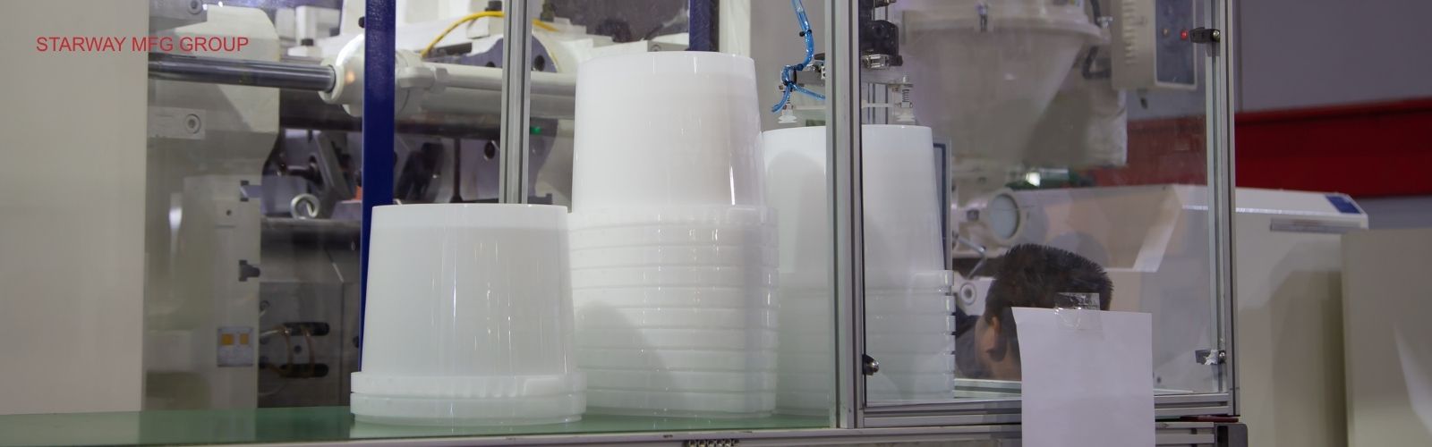
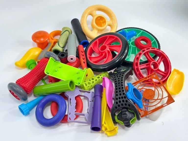
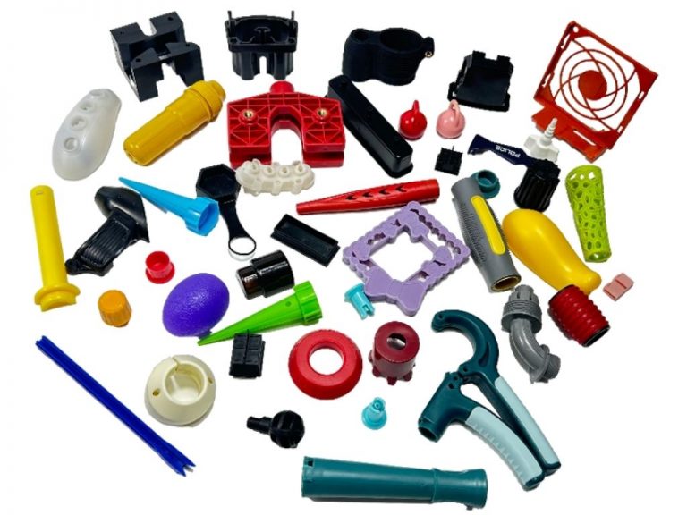
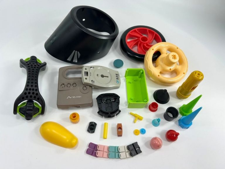
The process is widely used for automotive components, medical device housings, electronics enclosures, industrial equipment parts, consumer products, connectors, brackets, clips, caps, and precision plastic components. It is especially suitable when the design requires repeatability, moderate-to-high production volume, consistent dimensions, and professional surface finish.
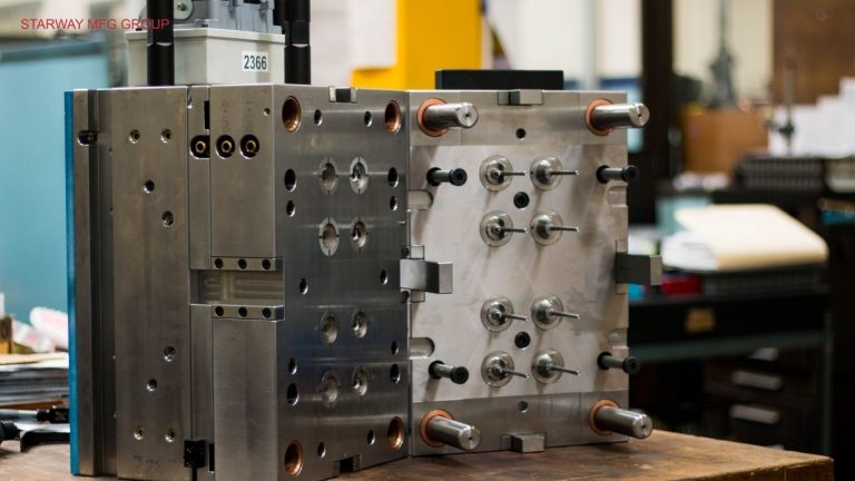
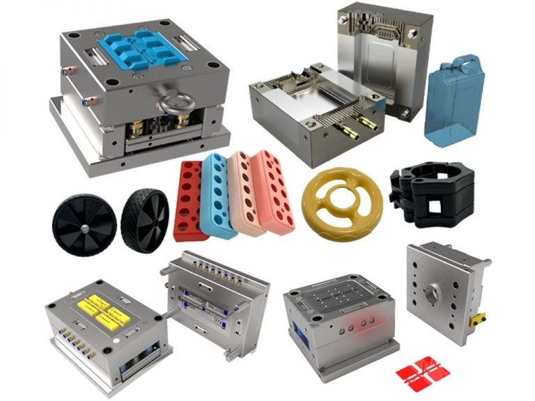
The mold is the heart of the process. A typical injection mold includes a cavity side, core side, parting line, runner system, gate, sprue, cooling channels, ejector pins, and sometimes sliders or lifters for undercuts. Mold tooling design directly affects part quality, cycle time, injection molding cost, and long-term production stability.
Compared with CNC machining or 3D printing, injection molding usually requires higher upfront tooling investment. However, once the mold is completed, the unit cost per part can become very competitive, especially for thousands or millions of parts. This is why many OEMs use low-volume or prototype injection molding for validation before moving into production tooling.
For engineers and buyers, the key is to treat injection molding as a complete manufacturing system rather than a single machine operation. Material selection, wall thickness, draft angle, gate position, cooling design, clamping force, shrinkage, and tolerance requirements must all be considered before cutting steel.
The injection molding process may look simple from the outside, but each stage has a major impact on final part quality. A stable process requires proper tooling, correct material preparation, controlled machine parameters, and experienced process engineers.
Every successful project starts with design for manufacturability (DFM). Engineers review the 3D model, drawings, tolerance requirements, material requirements, cosmetic surfaces, assembly features, and annual volume forecast. Important design factors include:
A practical DFM review can prevent expensive mold rework later. For example, a housing with thick corners may look strong in CAD, but it may cause sink marks during production. Reducing wall thickness, adding ribs, or changing gate location can improve manufacturability.
Injection molding materials are usually thermoplastic resins such as ABS, PP, PC, Nylon (PA), POM, PEEK, TPU, and PMMA. Each polymer has different strength, flexibility, heat resistance, chemical resistance, shrinkage rate, and surface appearance.
Some materials require drying before molding. Nylon, PC, PMMA, TPU, and PEEK are moisture-sensitive. If the resin is not dried properly, the part may show bubbles, silver streaks, poor mechanical strength, or surface defects. Material selection should consider:
The injection mold, or tooling, is custom-built for the part geometry. Tool steel, aluminum tooling, or pre-hardened steel may be selected depending on production volume, surface finish, expected tool life, and budget. A typical mold includes:
| Mold Component | Function | Design Impact |
|---|---|---|
| Mold cavity and core | Form the external and internal geometry of the part | Controls part shape, surface quality, and dimensional accuracy |
| Runner system | Guides molten resin from the sprue to the gate | Affects material waste, pressure loss, and cycle efficiency |
| Gate | Entry point into the mold cavity | Influences weld lines, flow marks, and gate vestige |
| Cooling channels | Remove heat from the part and mold | Strongly affects cycle time, warping, and shrinkage |
| Ejector pins | Push the finished part out of the mold | Must avoid cosmetic or functional damage |
| Sliders and lifters | Create undercuts or side features | Add complexity and tooling cost |
Molds can use cold runner or hot runner systems. Cold runner molds are often simpler and lower cost, but they may generate more material waste. Hot runner molds reduce runner scrap and improve cycle efficiency, but they increase tooling complexity and maintenance requirements.
Once the mold is installed in the molding machine, the clamping unit closes the mold with enough force to resist injection pressure. The required clamping force, or tonnage, depends on projected part area, resin type, flow length, cavity pressure, and number of cavities.
The injection unit then melts the resin pellets and injects the molten polymer into the mold cavity through the sprue, runner, and gate. Parameters such as melt temperature, injection speed, injection pressure, and screw position must be controlled carefully.
If the injection pressure is too low, the part may have a short shot. If the pressure is too high, flash may appear at the parting line. If the injection speed is not optimized, flow marks, burn marks, or weld lines may become visible.
After the cavity is filled, the machine applies holding pressure to compensate for material shrinkage as the polymer cools. This stage helps improve dimensional stability and reduce voids or sink marks.
Cooling is often the longest part of the cycle time. Efficient cooling channel design can reduce cycle time while improving part consistency. Poor cooling can cause warping, uneven shrinkage, and unstable dimensions.
Typical cycle time may range from 15 seconds to 90 seconds, depending on part size, wall thickness, resin type, mold temperature, and cooling efficiency. Large parts or engineering plastics may require longer cycles.
After the part has cooled enough, the mold opens and the ejector system pushes the part out. Ejector pins, stripper plates, or air ejection systems may be used depending on the part design.
Ejection must be carefully designed. If the part does not have enough draft angle, it may stick to the core. If ejector pins are too small or poorly positioned, the part may deform or show visible ejector marks.
After molding, parts may go through trimming, visual inspection, dimensional inspection, ultrasonic welding, heat staking, painting, silk-screen printing, pad printing, plating, or assembly. For production projects, quality control may include:
This step-by-step approach helps reduce technical risk and supports better communication between the customer, tooling engineer, molding technician, and quality team.
STARWAY offers custom injection molding with DFM support, mold tooling, and fast lead times.
STARWAY MFG GROUP provides engineering-driven plastic injection service for global OEM customers who need reliable molded plastic parts, custom tooling, and multi-process manufacturing support.
Starway supports projects from the early design stage. The engineering team reviews part geometry, wall thickness, draft angle, material selection, gate position, tooling structure, shrinkage risk, and assembly requirements before production starts. This helps customers reduce avoidable tooling changes and improves the chance of achieving stable production after mold trials.
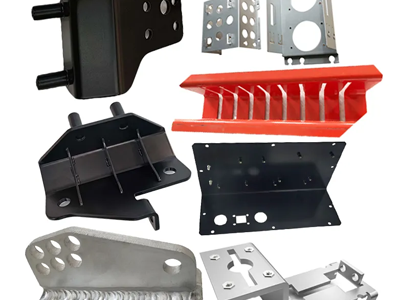
Many OEM projects are not plastic-only. A product may include injection molded housings, CNC machined metal inserts, sheet metal brackets, fasteners, surface finishing, and final assembly. Starway’s capabilities include:
| Capability | Customer Benefit |
|---|---|
| Custom injection molding | Molded plastic parts from prototype to production |
| Mold tooling design | Better control of part quality, cost, and lead time |
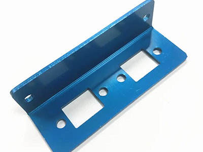
| CNC machining | Machined inserts, fixtures, and precision components |
| Sheet metal fabrication | Brackets, frames, enclosures, and structural parts |
| Assembly and packaging | Reduced supplier management complexity |
This integrated model helps procurement teams simplify sourcing and reduce coordination risk.
Starway serves customers in North America, Europe, and Australia, where documentation, repeatability, and inspection discipline are critical. Quality control can include incoming material inspection, First Article Inspection, in-process inspection, final inspection, and packaging checks.
Typical molded part tolerances may range from ±0.05 mm to ±0.20 mm, depending on part size, resin, geometry, shrinkage, and tooling design. For critical dimensions, tighter control may be possible after DFM review and process validation.
For new product development, low-volume injection molding or prototype injection molding can help validate design, material, and assembly fit before committing to high-volume tooling. For production programs, multi-cavity molds, hot runner systems, automated ejection, and optimized cycle time can help reduce unit cost.
As a Chinese contract manufacturer serving international OEMs, Starway understands the importance of clear communication, engineering documentation, export packaging, lead time planning, and responsive project management.
Material selection is one of the most important decisions in custom injection molding. The resin affects strength, flexibility, surface finish, dimensional stability, shrinkage, mold temperature, cycle time, and cost. See our full materials list for details.
Processing temperatures vary by grade, supplier, additive package, and part geometry. Final settings should always follow the resin datasheet and be validated during trial molding.
| Material | Key Properties | Processing Temp | Shrinkage | Common Applications |
|---|---|---|---|---|
| ABS | Good impact strength, easy processing, good surface finish | 220–260°C | 0.4–0.8% | Housings, covers, consumer products, equipment panels |
| PP | Lightweight, chemical resistant, flexible | 200–260°C | 1.0–2.5% | Caps, containers, hinges, medical and industrial parts |
| PC | High impact strength, transparency, heat resistance | 260–320°C | 0.5–0.7% | Lenses, covers, protective housings, electronic parts |
| Nylon / PA | Wear resistant, strong, good fatigue resistance | 250–300°C | 0.7–1.5% | Gears, clips, bearings, mechanical components |
| POM | Low friction, high stiffness, good dimensional stability | 180–220°C | 1.8–2.5% | Precision gears, bushings, sliding parts |
| PEEK | High-performance, heat and chemical resistant | 360–400°C | 1.0–1.5% | Aerospace, medical, electrical, high-temperature parts |
| TPU | Flexible, abrasion resistant, elastic | 190–230°C | 0.8–1.8% | Seals, grips, protective parts, flexible components |
| PMMA | Clear, glossy, good optical properties | 220–260°C | 0.2–0.8% | Light guides, lenses, display covers |
Injection molding tolerances depend on many variables, including part size, material shrinkage, mold temperature, wall thickness, flow direction, gate location, and cooling design.
| Factor | Effect on Tolerance | Engineering Recommendation |
|---|---|---|
| Material shrinkage | High-shrinkage materials such as PP and POM are harder to control | Use accurate shrinkage data and validate during mold trial |
| Wall thickness | Uneven thickness causes sink and warping | Keep wall thickness uniform where possible |
| Mold temperature | Affects cooling rate and final dimensions | Use stable mold temperature control |
| Gate location | Influences flow pattern and packing pressure | Place gate based on function and cosmetic requirements |
| Cooling design | Uneven cooling creates dimensional variation | Optimize cooling channels during mold design |
| Part geometry | Long, thin, or complex parts may warp | Add ribs, adjust thickness, or modify design early |
For many industrial plastic parts, a practical tolerance range is ±0.05 mm to ±0.20 mm. Larger parts, flexible materials, glass-filled materials, or high-shrinkage resins may require wider tolerances. For critical features, tooling inserts, post-machining, or controlled molding conditions may be considered.
Plastic molded parts are used across many industries because they can combine low weight, complex shape, electrical insulation, corrosion resistance, and consistent quality. Common applications include:
Industries served include:
| Industry | Typical Molded Components | Key Requirements |
|---|---|---|
| Automotive | Clips, housings, brackets, interior parts | Heat resistance, repeatability, durability |
| Electronics | Enclosures, connectors, covers | Dimensional accuracy, insulation, surface finish |
| Medical Devices | Housings, covers, small components | Clean appearance, material traceability, consistency |
| Industrial Equipment | Guards, handles, panels, covers | Strength, wear resistance, stable supply |
| Robotics and Automation | Structural covers, gears, cable guides | Precision, durability, assembly fit |
| Green Energy | Electrical housings, protective covers | Weather resistance, flame-retardant options |
| Consumer Products | Housings, buttons, caps, grips | Appearance, color consistency, cost control |
Choosing the right plastic injection molding manufacturing partner is a major decision for buyers. The lowest quote is not always the lowest total cost. Tooling quality, engineering support, communication, process control, and quality documentation can significantly affect project success.
A reliable manufacturer should review your CAD files, drawings, material requirements, parting line, draft angle, wall thickness, gate location, tolerances, and expected production volume. A strong supplier should be able to explain:
Different projects require different tooling strategies.
| Tooling Option | Best For | Advantages | Limitations |
|---|---|---|---|
| Prototype mold | Design validation, low-volume production | Lower tooling cost, faster lead time | Shorter tool life, limited automation |
| Production mold | Stable mass production | Better durability, repeatability, efficiency | Higher upfront investment |
| Multi-cavity mold | High-volume production | Lower unit cost, higher output | Higher tooling complexity |
| Hot runner mold | High-volume or material-saving projects | Less runner waste, improved efficiency | Higher mold cost and maintenance |
| Insert mold | Plastic over metal inserts | Strong mechanical integration | Requires insert handling and positioning |
Injection molding cost usually includes tooling cost, material cost, machine time, labor, quality inspection, secondary processing, packaging, and shipping. Main cost drivers include:
A simple plastic cover may be relatively low cost. A complex part with undercuts, tight tolerances, high-temperature resin, insert molding, and cosmetic finish will cost more.
Both processes are useful, but they serve different purposes.
| Factor | Injection Molding | 3D Printing |
|---|---|---|
| Best use case | Repeatable production parts | Prototypes and low-volume design testing |
| Upfront cost | Higher due to mold tooling | Lower, no mold required |
| Unit cost at volume | Low | Usually higher |
| Material options | Wide range of production thermoplastics | Material selection depends on printing technology |
| Surface finish | High and repeatable | Often requires post-processing |
| Tolerance control | Strong when tooling and process are stable | Varies by printer and material |
| Lead time | Tooling takes longer | Faster for first prototype |
| Scalability | Excellent for mass production | Limited for high-volume production |
For early design validation, 3D printing is often useful. For repeatable production, better surface finish, and lower unit cost at volume, injection molding is usually the better option.
Before choosing an injection molding supplier, buyers should ask:
A good supplier should not simply accept every drawing without discussion. Experienced manufacturers identify risks early and help customers make better decisions before tooling investment.
A successful injection molding project depends on more than machine capacity. It requires the right product design, material selection, tooling strategy, process control, and quality management. For engineers, procurement managers, and product designers, early DFM review and supplier communication can reduce tooling risk, shorten development time, and improve production stability.
STARWAY MFG GROUP supports global OEM customers with custom injection molding, mold tooling design, material selection, quality inspection, assembly, and export manufacturing services. If you are developing a new plastic component or preparing for production, visit our Plastic Injection Molding Service page to request engineering support and a project quotation.
Share your CAD files and get DFM feedback plus a project quotation from our engineering team.


This website uses cookies to provide you with a personalized browsing experience and analyze website traffic. By clicking "Accept", you agree to our use of cookies.


 Global