
 Global
Housings and Enclosures
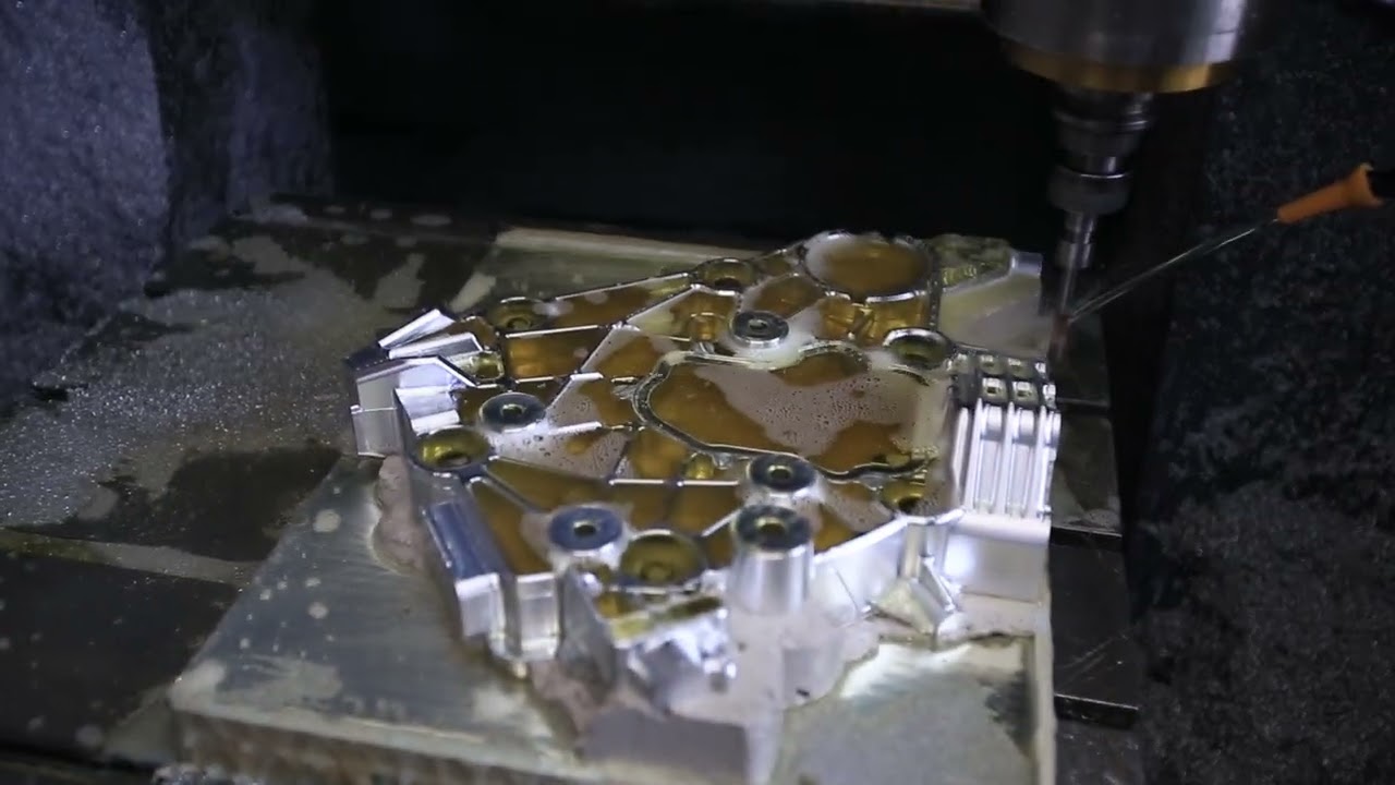
Review internal pockets, mounting faces and wall sections together. Identify the surfaces and openings that locate or support mating components.


Sheet Metal Fabrication Design Engineering Project management Assembly Rapid Prototyping Packaging Shipping & Delivery
CNC Machining Design Engineering Project management Assembly Rapid Prototyping Packaging Shipping & Delivery
Plastic Injection Molding Design Engineering Project management Assembly Rapid Prototyping Packaging Shipping & Delivery
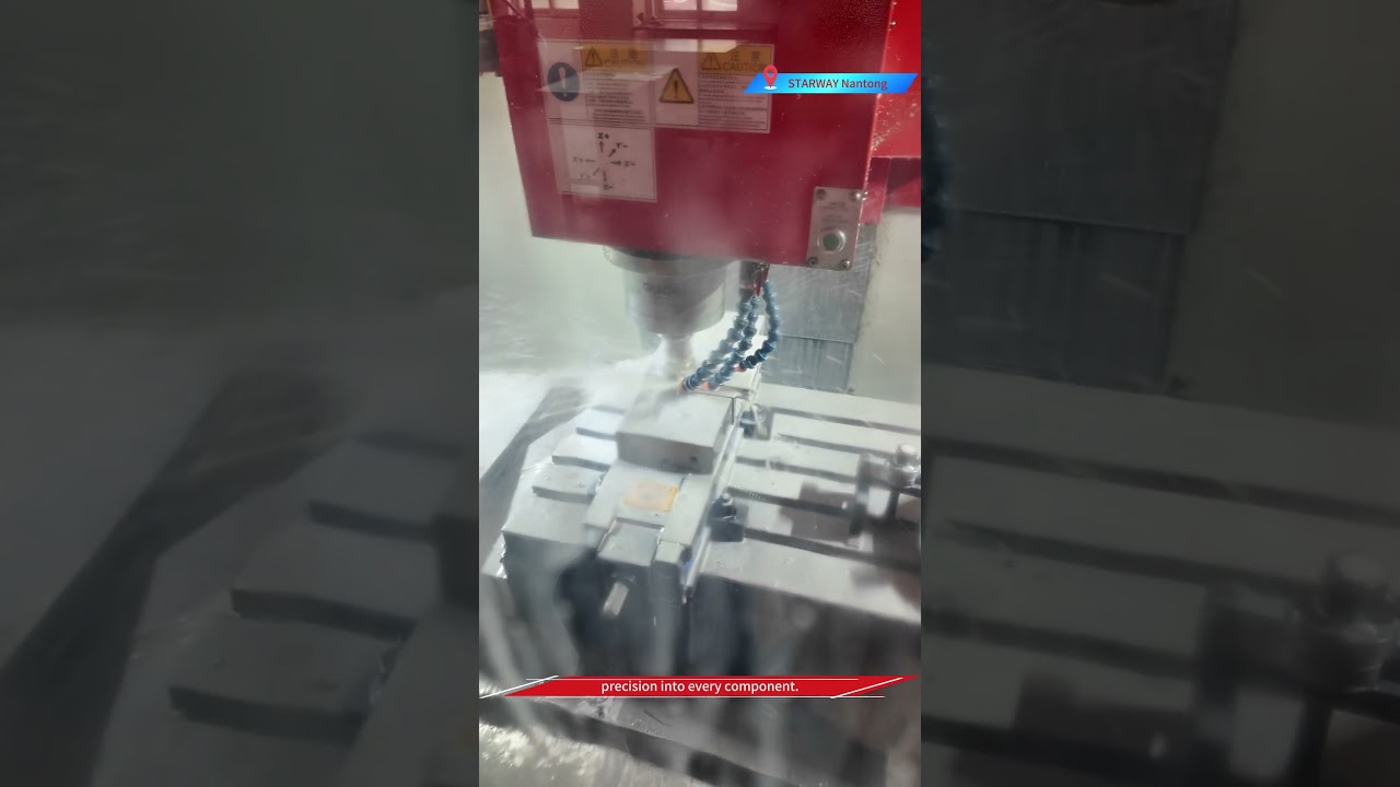
Custom CNC milling services for housings, plates and multi-face components, with tool access and critical features reviewed first.
What to include
Share your drawings, critical features and hole relationships for review.
Plan around the relationships that matter
Pockets, holes and features on different sides decide how CNC milled parts are held, machined and inspected.
Review internal pockets, mounting faces and wall sections together. Identify the surfaces and openings that locate or support mating components.
Define hole patterns, locating features and reference faces. Mark the flatness and positional requirements that control assembly fit.
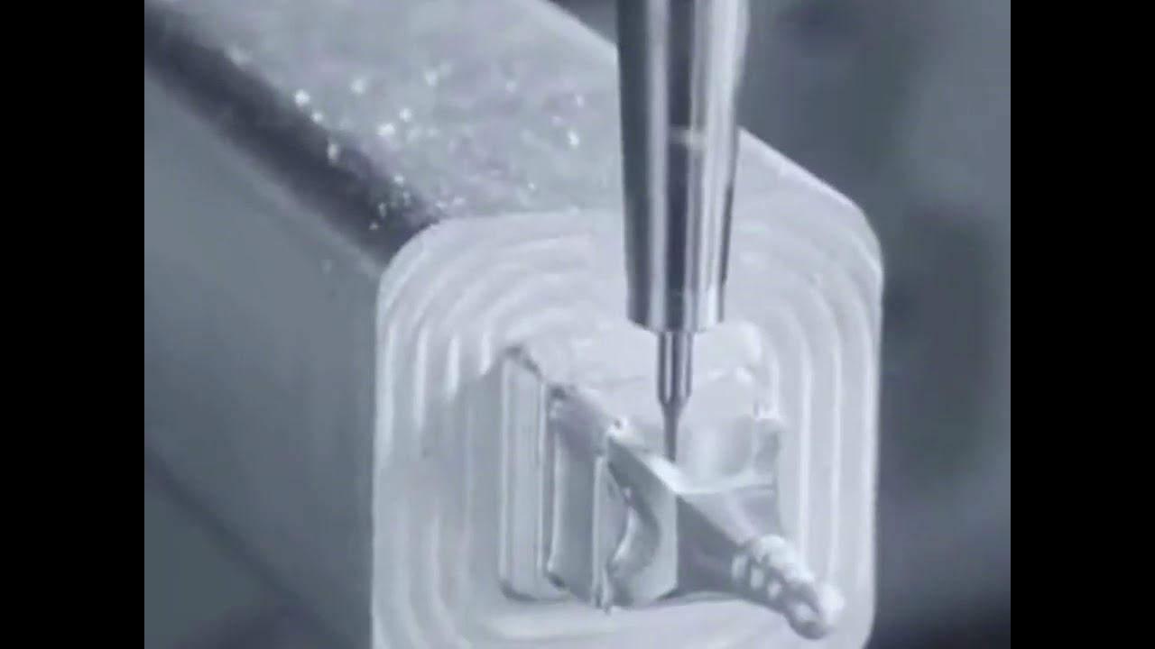
Specify pocket depth, internal radii and bottom features. Tool reach and chip removal may affect access, machining time and achievable surface quality.
Identify angled faces, contours and features on different sides. Their relationships help determine setup planning and whether additional axes are useful.
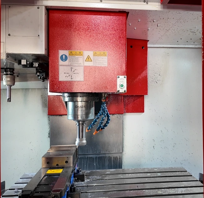
Choose the setup around feature access
The right setup depends on feature access and geometry; more axes do not automatically lower cost or tighten tolerances.
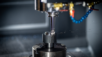
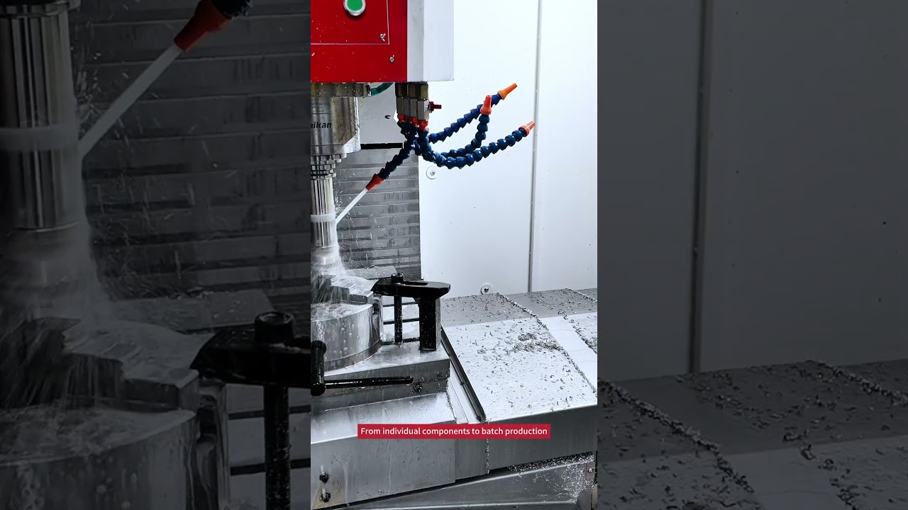
Suitable for many plates, brackets and housings with accessible faces, holes and pockets. Features on additional sides may require repositioning, with fixtures and datums planned around the critical relationships.
Review Focus:Accessible faces / Pocket depth / Repositioning / Datum control
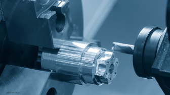
5-axis milling for complex parts can improve access to angled features and contoured surfaces. Depending on the geometry, indexed or simultaneous machining may reduce repositioning or allow a more suitable tool orientation.
Review Focus:Angled features / Surface contours / Tool access / Setup reduction
For 5 axis CNC machining, the required motion and setup strategy are selected during technical review. Not every part requires simultaneous five-axis cutting or can be completed in one setup.
Review the cost drivers early
Review tool access, material removal, workholding and inspection early to simplify production without losing function.

Deep, narrow pockets and small corner radii can require longer or smaller tools and additional passes. Where function allows, review larger radii and improved access.

Thin sections may deflect during machining or move after material removal. Review wall geometry, support and machining sequence around the required final condition.
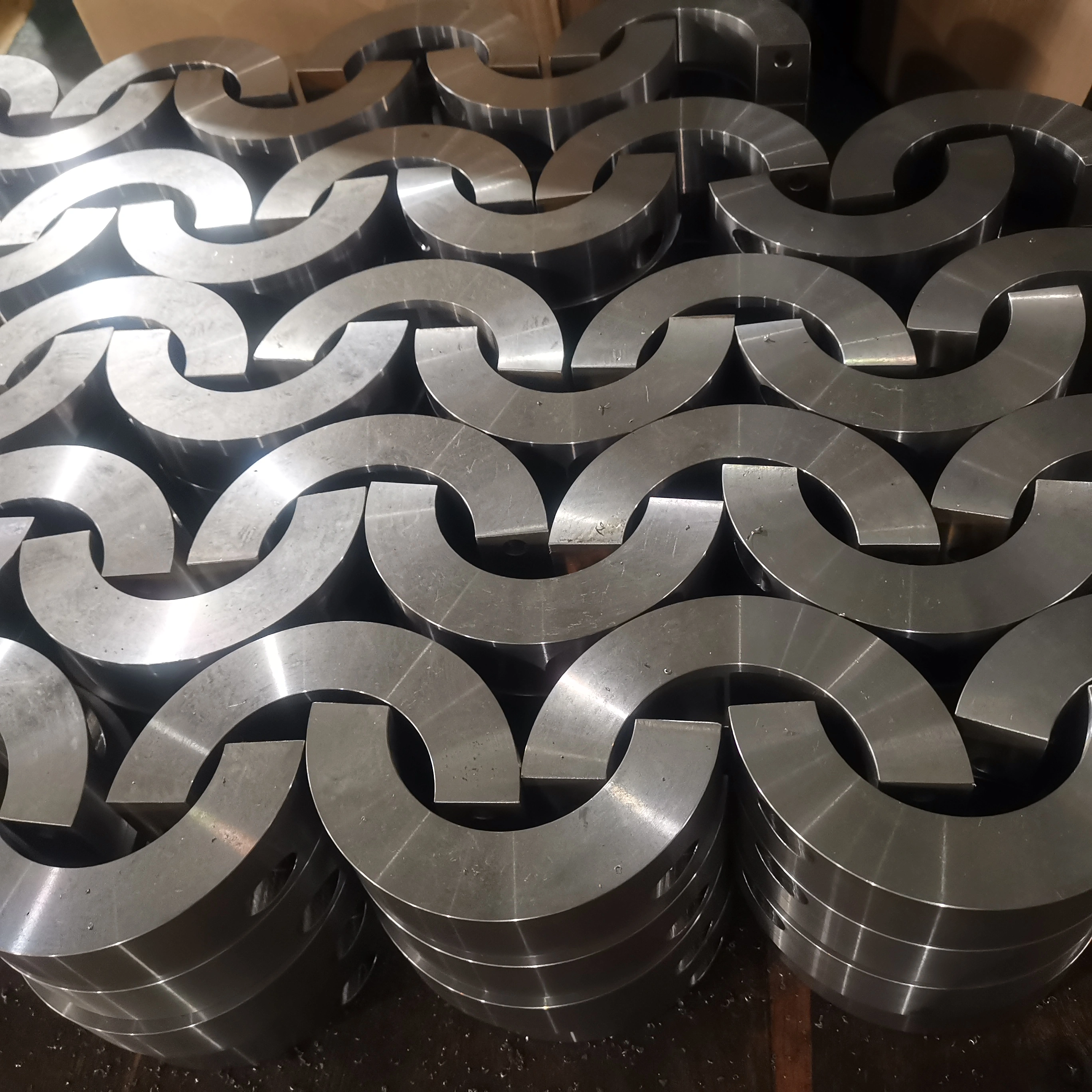
Additional setups introduce workholding and alignment work. Identify which cross-face relationships are critical so the route can prioritize them.
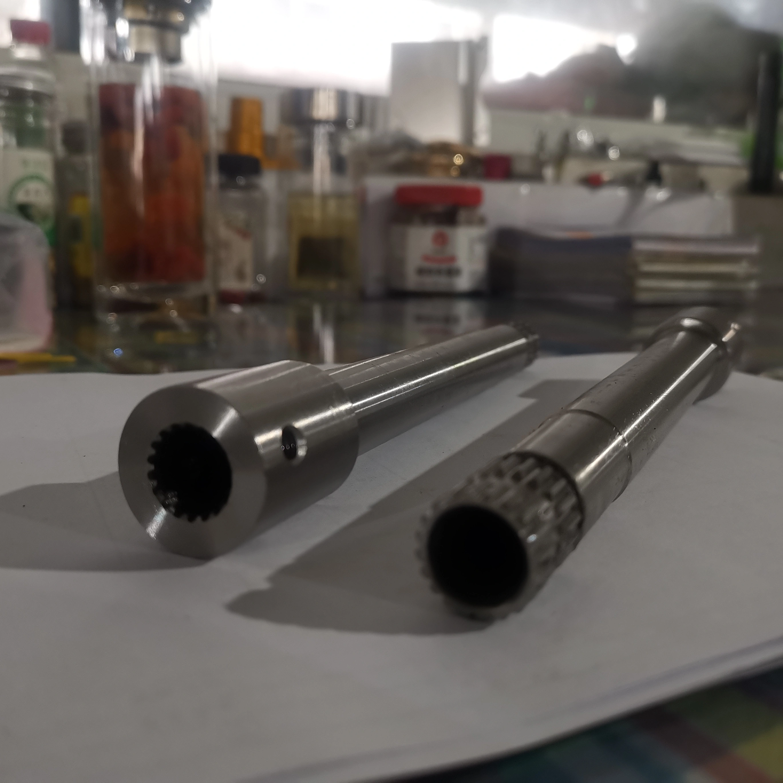
Apply tight tolerances and fine roughness only where function requires them. Include datums and acceptance criteria so machining and inspection effort can be assessed accurately.
Design changes are proposed for review and require approval before the drawing is revised or production begins.
Share your drawing, critical features and hole relationships to discuss machining access, setup planning and cost drivers.
Keep the requirements connected
At STARWAY MFG GROUP, material, machining, finishing and inspection are reviewed together to keep critical features aligned.
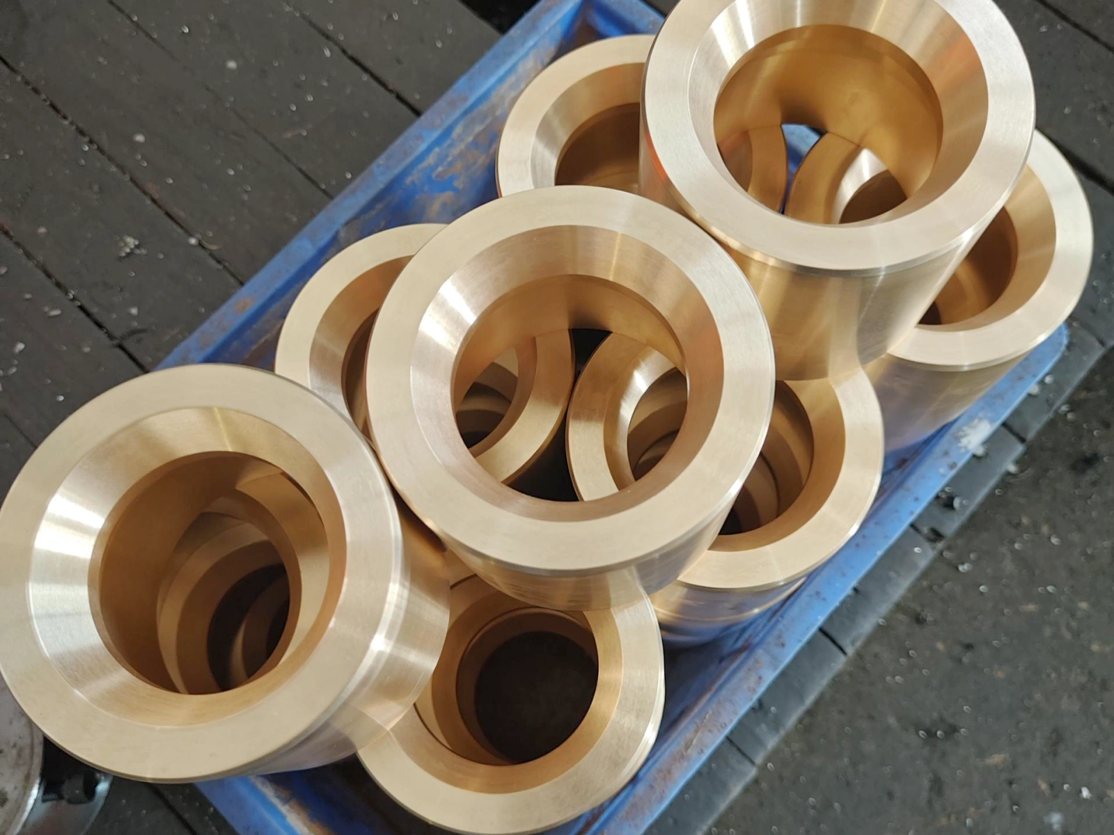
Confirm the grade, condition and documentation needed for your part, including metal and engineering plastic options.
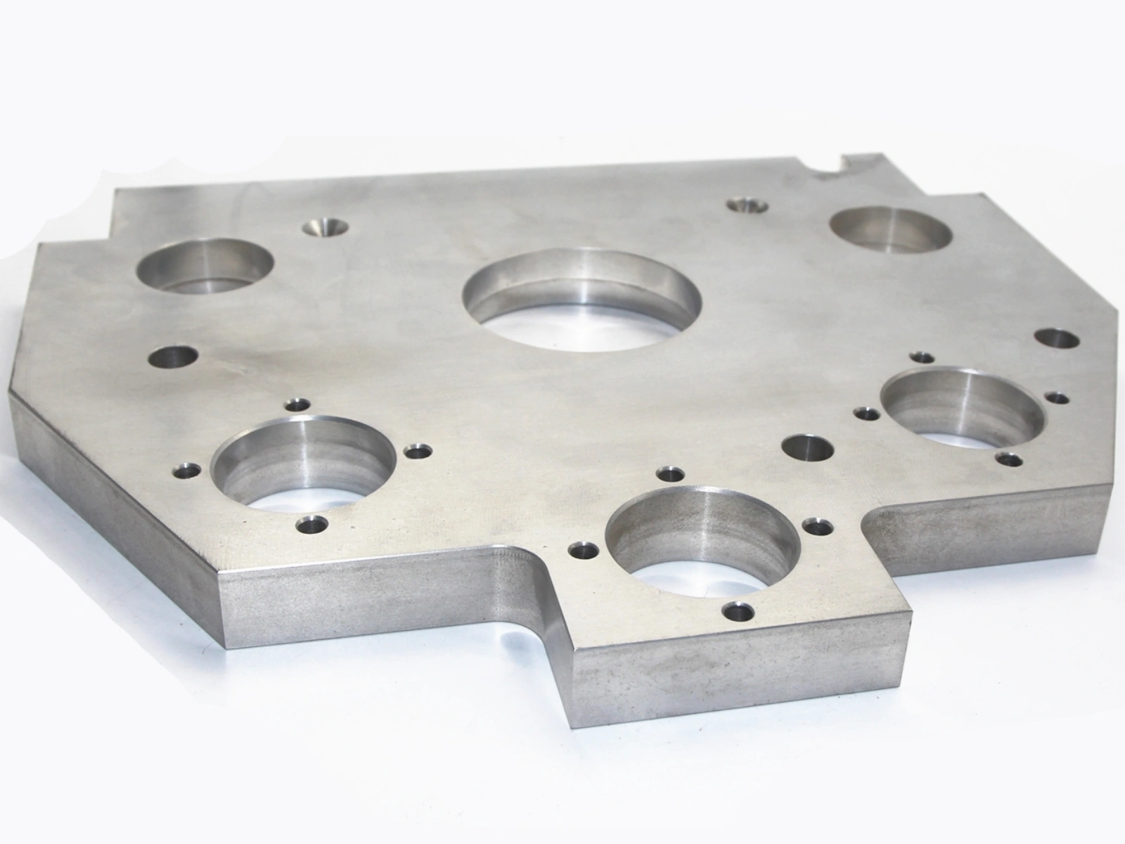
Plan tool access, workholding and machining sequences around pockets, hole relationships and mating surfaces.
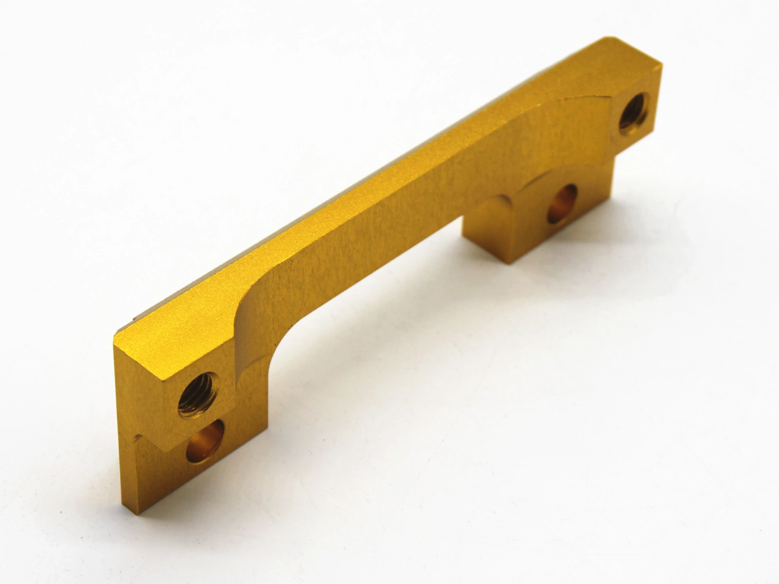
Review the specified finish, masking needs and coating allowance to protect threads, bores and functional surfaces.

Define checks for critical dimensions, hole positions and surface requirements, with reporting agreed for the project.
Send your drawing and final delivery requirements so we can review them together.
Documented project planning
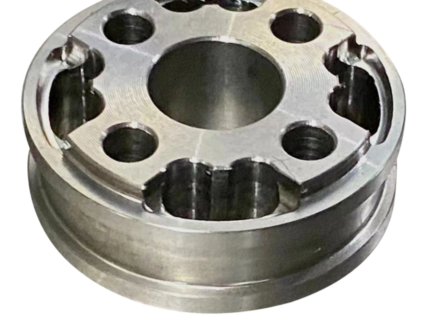
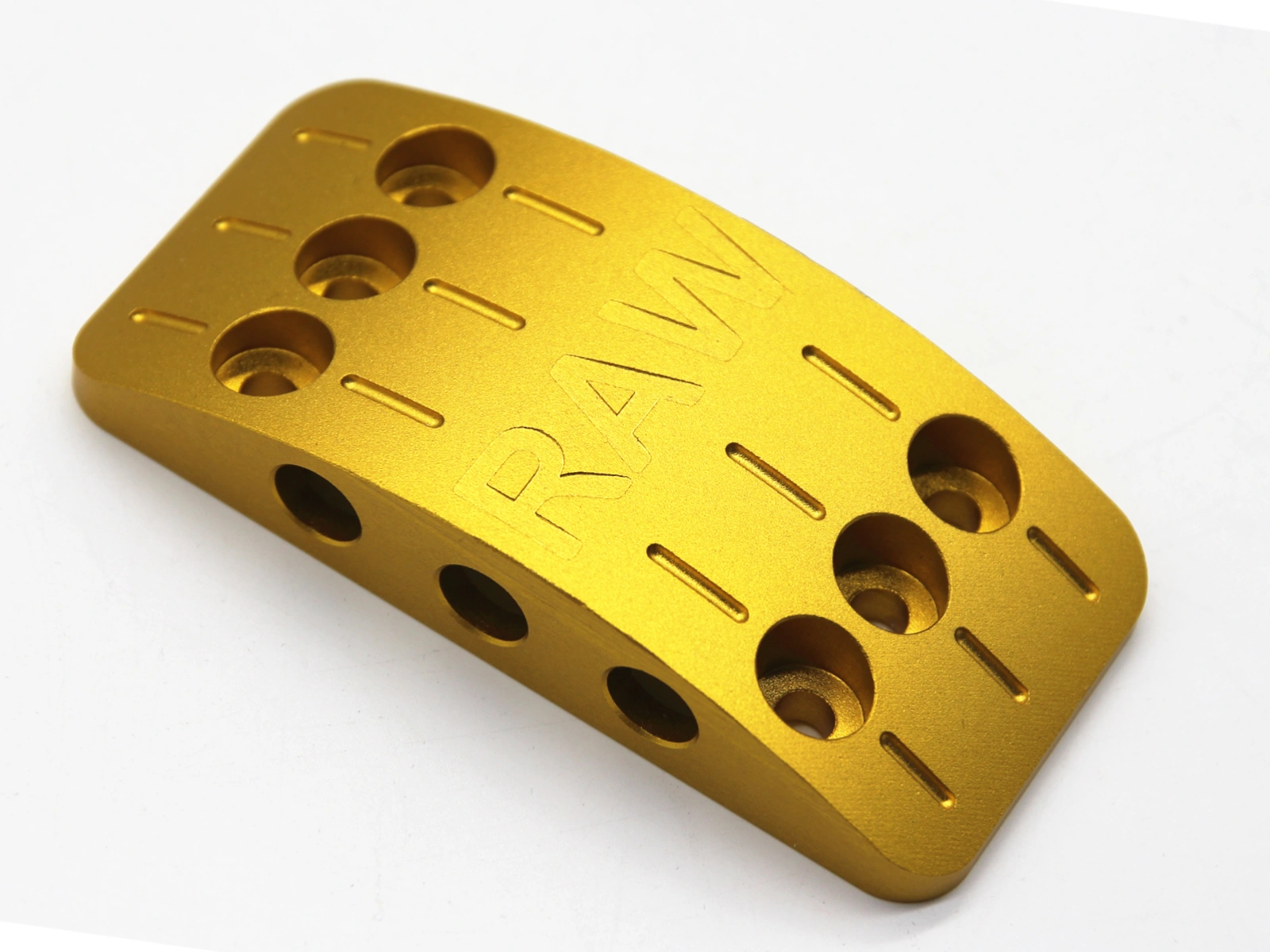
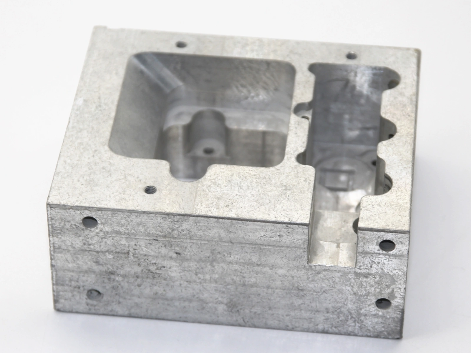
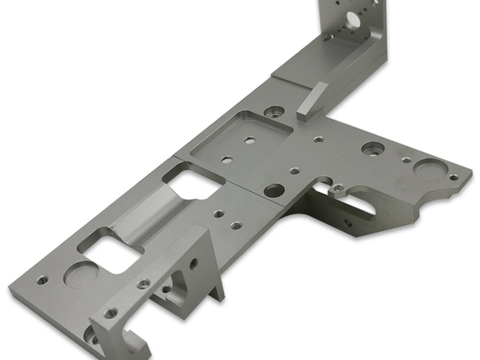
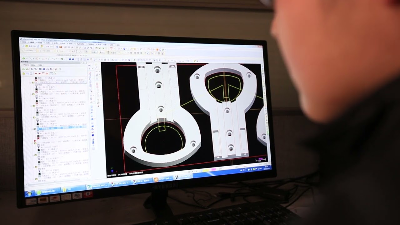
See how part geometry, setup planning and inspection requirements are brought together for a documented milling project.

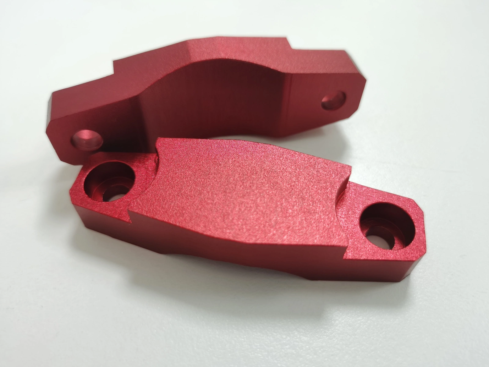
Material: POM
Application: Electronic components

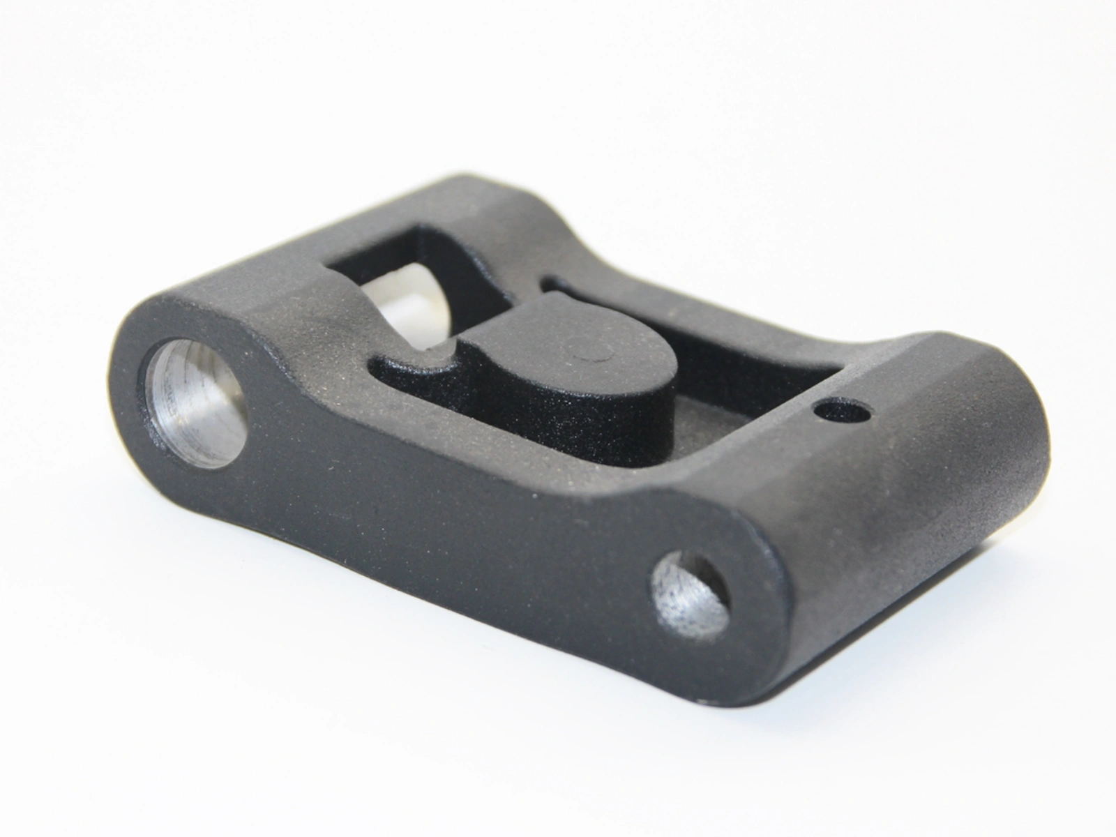
Material: Aluminum
Application: Prototype validation

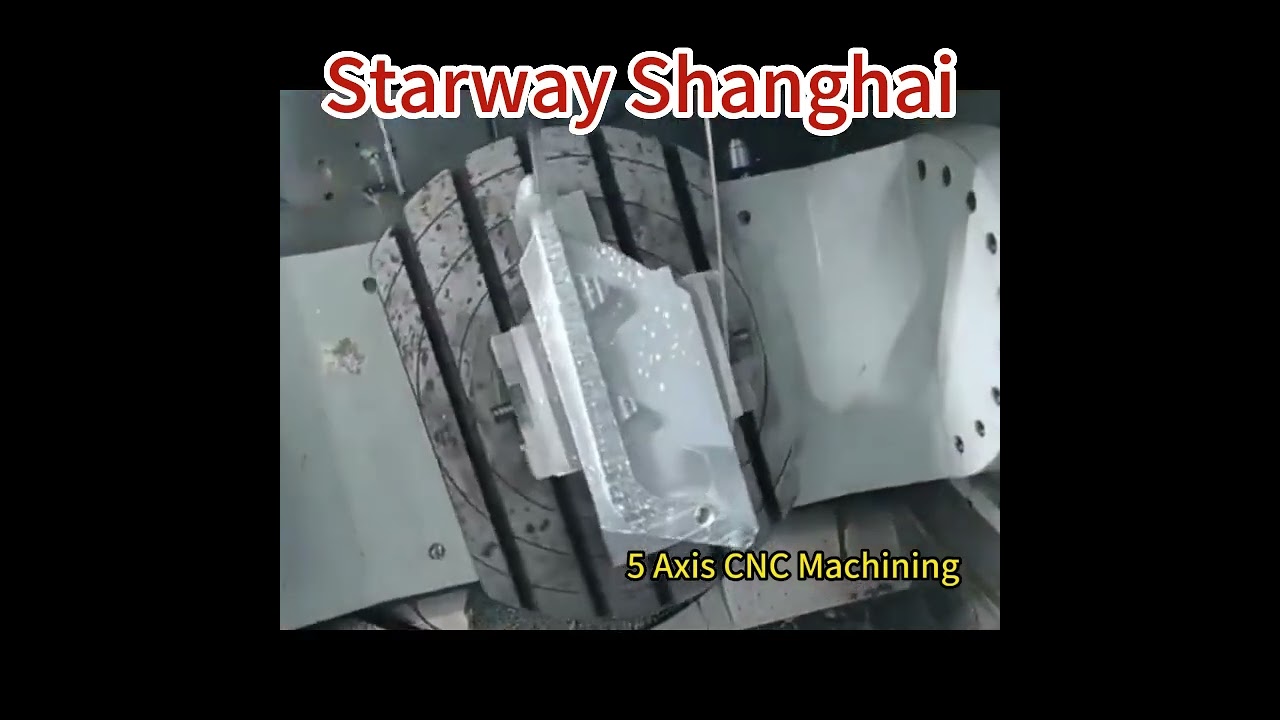
Material: Aluminum alloy
Application: Automotive components

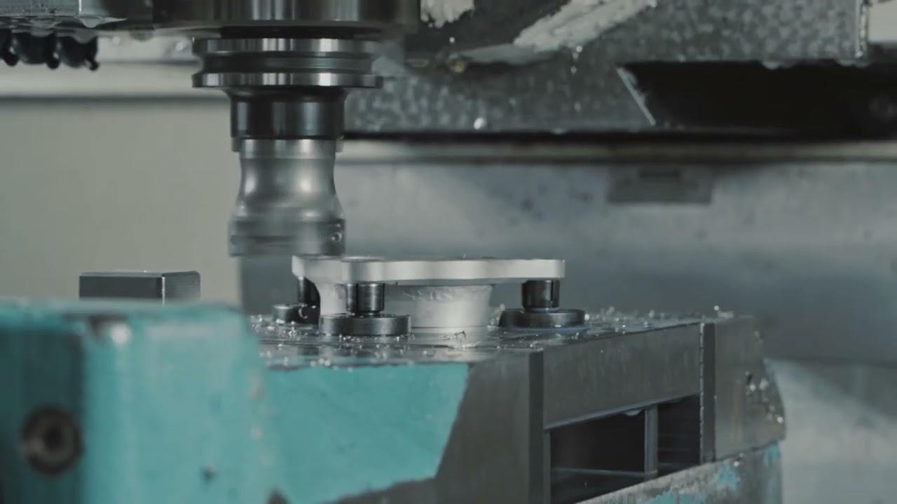
Material: Stainless steel
Application: Industrial equipment
Project review
Share your drawings, critical features and hole relationships for review.
Frequently asked questions
CNC milling suits housings, plates, brackets and components with pockets, hole patterns, flat faces or contoured surfaces. Features on multiple sides can also be reviewed. Suitability depends on material, overall dimensions, tool access, workholding and the relationships between critical features.
Three-axis milling suits many parts with accessible faces, holes and pockets. Five-axis milling may help with angled features, complex contours or restricted tool access. Indexed or simultaneous machining is selected around the geometry; additional axes do not automatically guarantee tighter tolerances or a single setup.
Deep pockets and small internal radii may require longer or smaller tools, additional passes and more machining time. Thin walls can need extra support and careful sequencing. Where function allows, changes to radii, wall geometry or access may simplify production. Any design change requires approval.
Provide a dimensioned drawing showing critical sizes, datum references and geometric tolerances where required. Identify hole patterns, locating bores and mating faces that must relate to one another. Achievable tolerances are reviewed for the specific material, geometry, setup and final delivery condition.
Options include aluminum, stainless steel, carbon and alloy steel, brass, copper and engineering plastics. Provide the exact grade and condition. Finishes such as anodizing, plating, blasting or coating are reviewed for compatibility. Mark functional surfaces and specify whether dimensions apply before or after finishing.
Inspection follows the approved drawing and agreed plan. Checks may cover hole positions, bore sizes, mating-face geometry, threads and roughness. Methods are selected for the features being measured. Specify first-article reports, dimensional records, sampling or any required 100% checks during quotation review.
Both prototypes and production batches can be reviewed. Lead time depends on drawing readiness, material availability, geometry, quantity, finishing and inspection. Provide the quantity required at each stage and your target date. The schedule, including any sample approval stage, is confirmed after technical review.
Send a STEP/STP or IGES/IGS model and a dimensioned PDF drawing where available. Include material, quantity, revision, critical features, hole relationships, finish and inspection requirements. Add mating-part references where they affect acceptance. If files are incomplete, identify what still needs clarification.

This website uses cookies to provide you with a personalized browsing experience and analyze website traffic. By clicking "Accept", you agree to our use of cookies.