
Sheet Metal Fabrication Design Engineering Project management Assembly Rapid Prototyping Packaging Shipping & Delivery
CNC Machining Design Engineering Project management Assembly Rapid Prototyping Packaging Shipping & Delivery
Plastic Injection Molding Design Engineering Project management Assembly Rapid Prototyping Packaging Shipping & Delivery
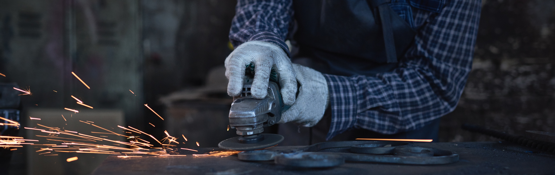
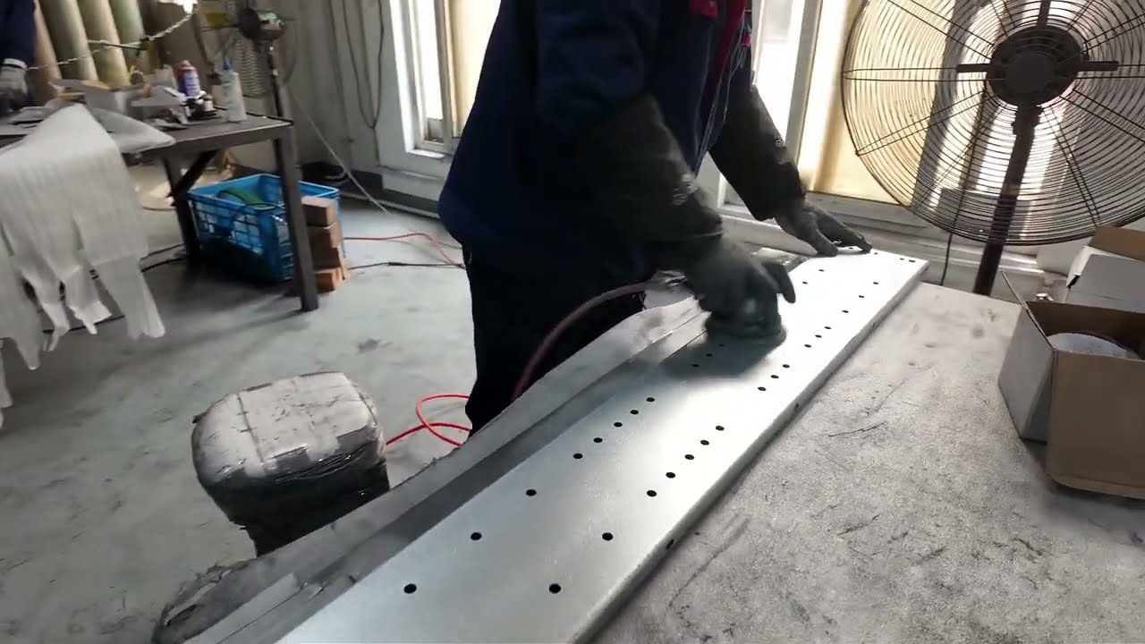
Sheet metal grinding and polishing services for welds and visible surfaces. Share your finish reference, grain direction and cosmetic requirements.
✓ Weld grinding and blending ✓ Brushed and polished surface review ✓ Reference-based appearance approval

Select the treatment around the joint, base material and final appearance. Finishing must also preserve the features needed for fit and function.
| Option | What It Addresses | What to Specify |
|---|---|---|
| Weld Grinding | Weld reinforcement and local surface irregularities | Weld requirements, permitted removal and surrounding geometry |
| Weld Blending | Transition between the weld and adjacent surface | Acceptable weld visibility and reference appearance |
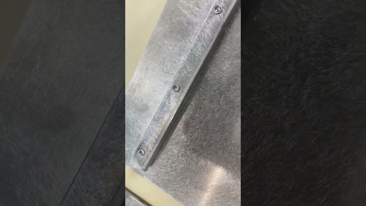
| Brushing | Directional texture across selected surfaces | Grain direction, texture reference and matching faces |
| Polishing | Surface refinement and gloss | Reference sample, cosmetic zones and acceptance conditions |
For stainless steel polishing, approve the weld repair appearance before batch production. Limit removal on aluminum and protect coated sheet.
A finish name alone does not define acceptance. Combine marked drawings with a reference sample and agreed inspection conditions.
Identify visible faces, hidden areas and surfaces that must remain untreated. Mark threads, mating faces, edges and other features that need protection during finishing.
Use arrows on the drawing to show brushing direction. Identify adjoining faces or panels where grain alignment and appearance must be reviewed together.
Provide a physical sample or reference photographs for review. Photos support initial discussion, while appearance-critical work may require an agreed physical sample before batch production.
Ra is required, specify the value, unit, measurement area and applicable method. Agree separately on visual texture, gloss and acceptable local variation.
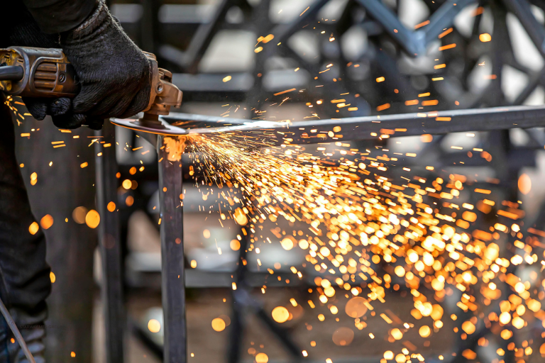
Surface protection continues after finishing. Review packing around the cosmetic areas, part geometry and shipping conditions.
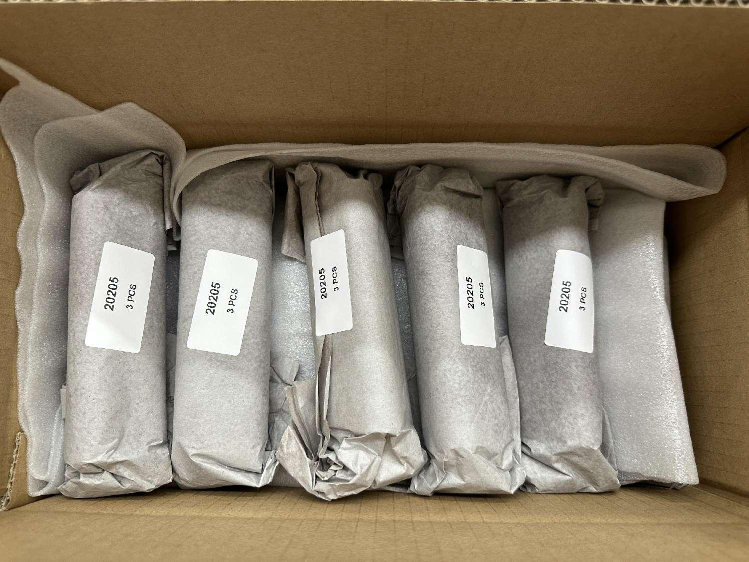
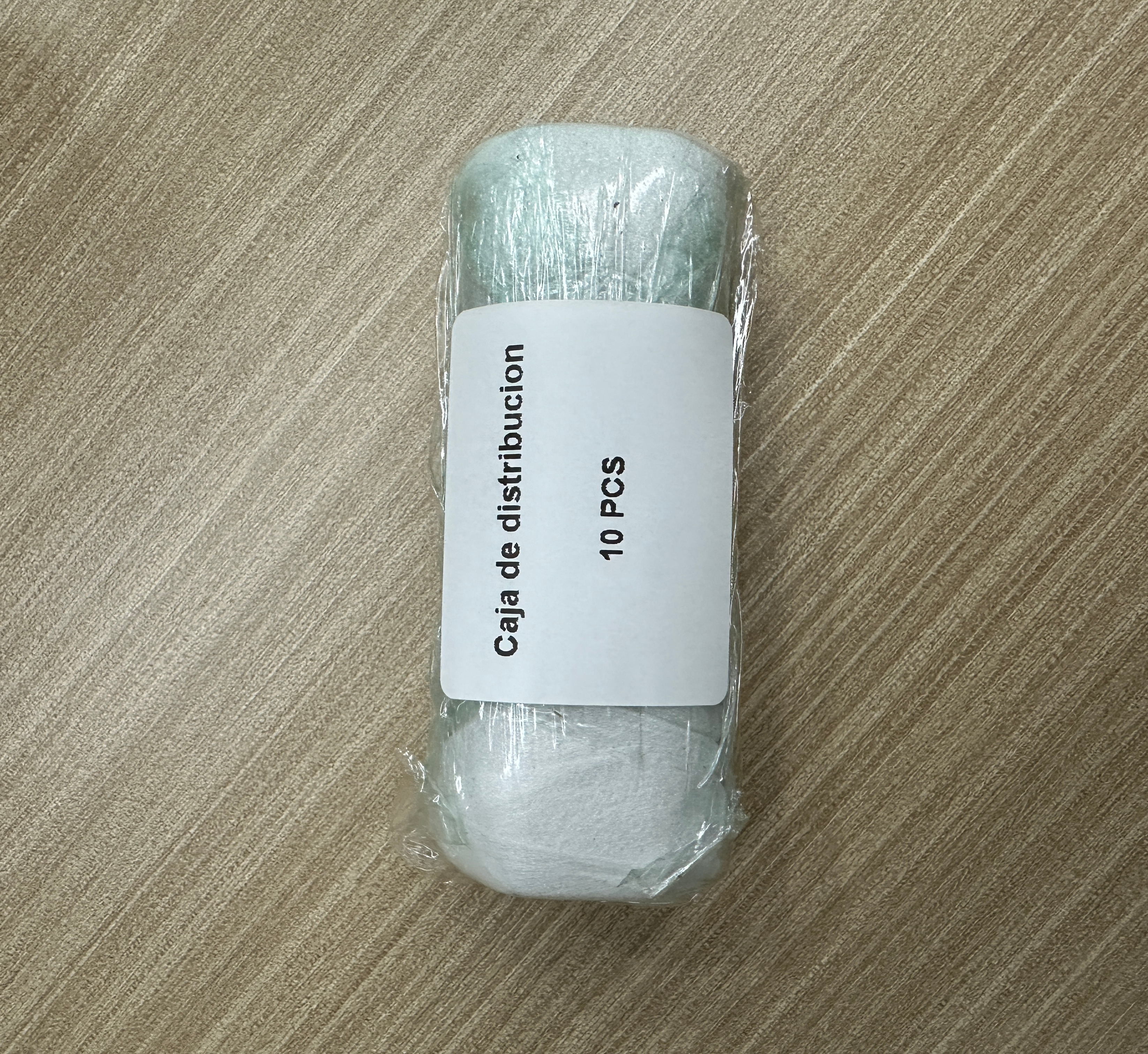
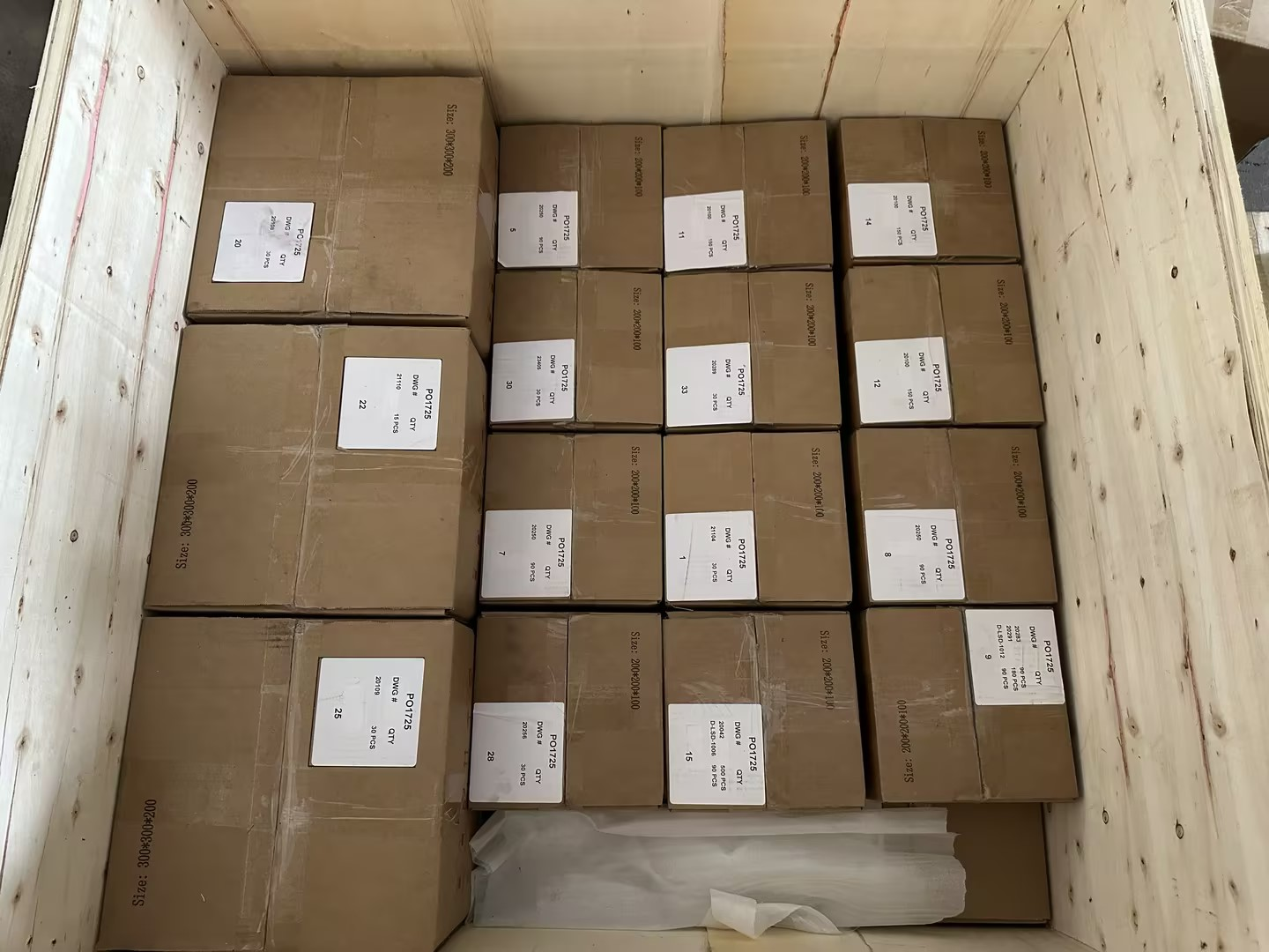
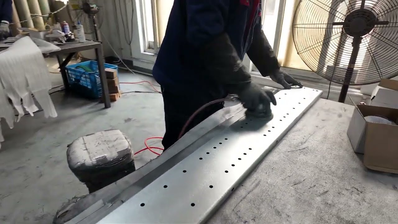
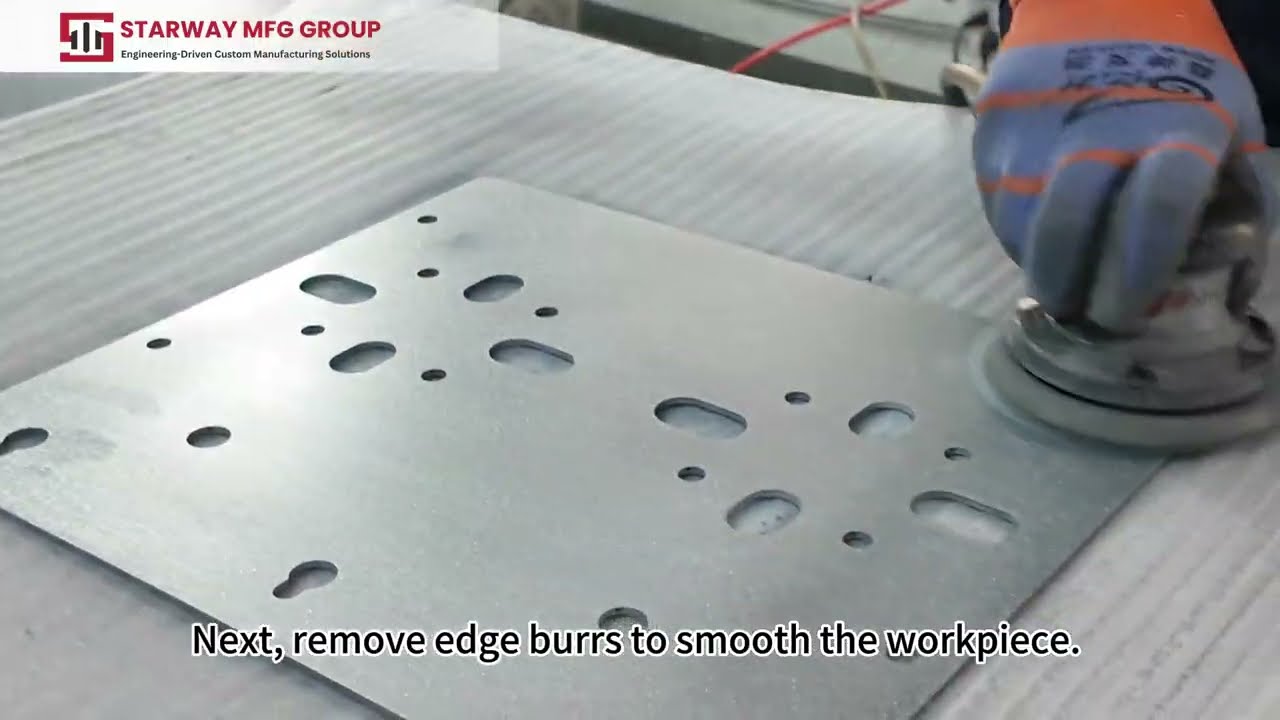
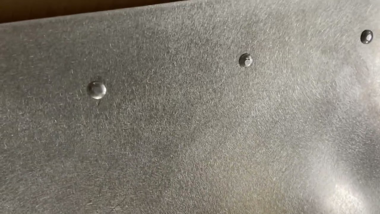
Compare the same part before and after finishing, with attention to weld transition, grain direction and the agreed cosmetic areas.
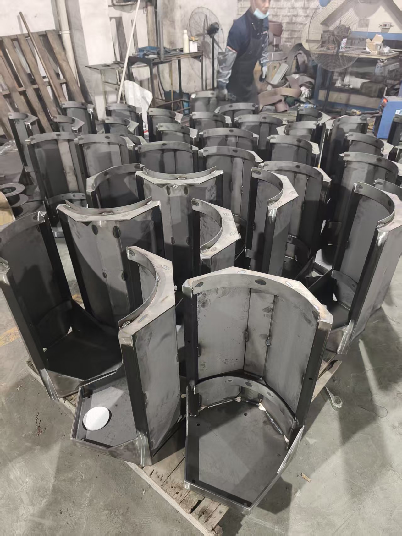
Material: Q235 Carbon Steel Plate Thickness: 5 mm Part Type: Welded Sheet Metal Assembly Final Appearance: Red-Coated Surface.
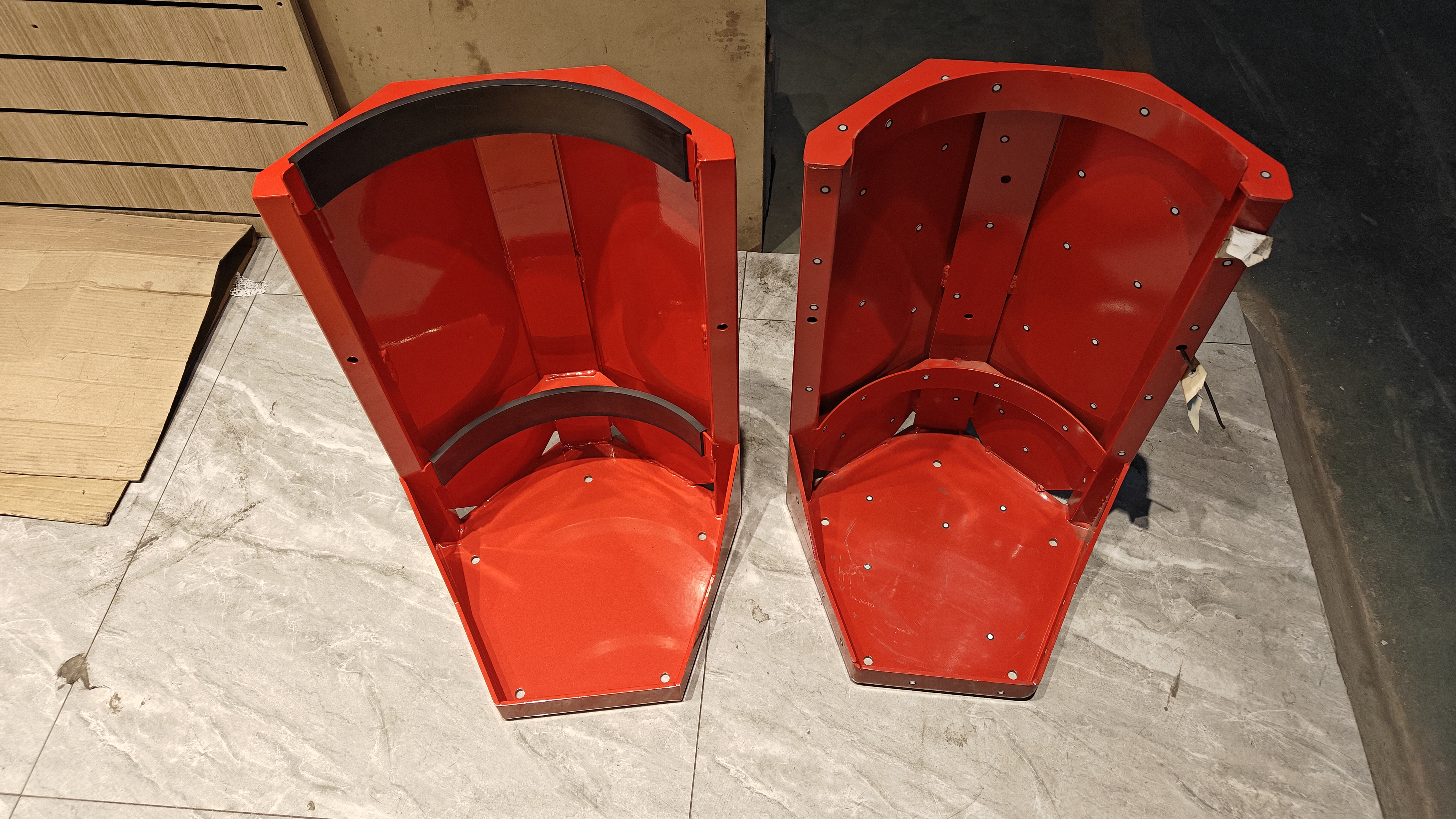
These 5 mm Q235 assemblies illustrate the progression from welded fabrication to a red-coated finish. The grinding scope should follow the drawing, with attention to specified weld areas, edges and visible transitions.
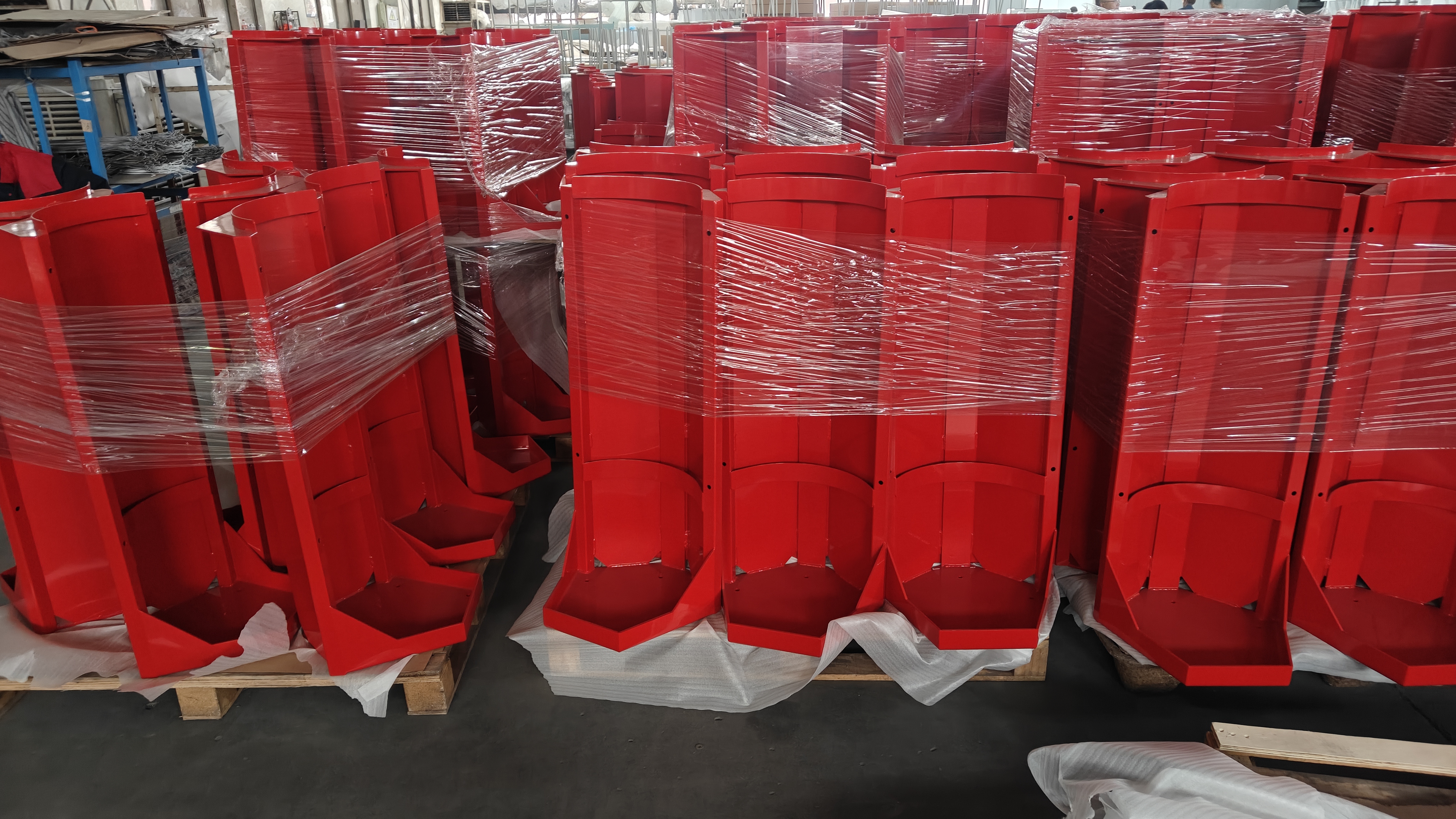
Local weld and edge treatment, preservation of required joint geometry, and surface preparation for the specified coating process.
We review weld grinding, weld blending, brushing and polishing for sheet metal parts and assemblies. The finishing route depends on the material, starting surface, joint geometry and required appearance. Mark the areas to be treated and provide a finish reference where appearance is important.
Yes, subject to the joint design and weld requirements. Specify whether welds should remain visible, be blended into the surrounding surface or be ground flush. Material removal must preserve the required joint and part geometry. For cosmetic joints, agree on the local finish appearance before batch production.
Mark the surfaces to be brushed and add arrows showing grain direction on the drawing. Provide a reference sample or photographs showing the required texture. Identify adjacent panels, corners or repaired weld areas where appearance must be reviewed together. A grit designation alone may not fully define the finished appearance.
We can review your reference and assess a suitable finishing route. The result depends on material, initial surface condition, part geometry and access around welds or corners. Photos help with initial discussion, but a physical sample may be needed for critical appearance approval. Agree on acceptable variation before production.
No. Ra describes measured surface roughness; it does not fully define gloss, grain direction or visual uniformity. If roughness is required, specify the value, unit, measurement location and applicable method. Define cosmetic acceptance separately using a reference sample and agreed viewing conditions.
Some scratches and local marks can be reduced, depending on their depth and the permitted material removal. Deep defects may require another solution. Preparation for coating should follow the specified coating process; mirror polishing is not automatically required. On pre-coated sheet, review any treatment that could damage the protective layer.
Agree on cosmetic zones, reference samples and inspection conditions before production. Check roughness separately where specified. Packing should prevent contact and movement that could mark finished faces, using suitable wrapping, separators and support. Include any special handling or moisture-protection requirements in the project review.
Send drawings, material and thickness, quantity, finish references and photographs of the starting surface where available. Mark cosmetic zones, grain direction and required weld treatment. Include any Ra specification, packing needs and target delivery date. Cost and lead time depend on surface condition, access, finish level and approval needs. Each uploaded file must be smaller than 130 MB.

This website uses cookies to provide you with a personalized browsing experience and analyze website traffic. By clicking "Accept", you agree to our use of cookies.



 Global